s Welcome to STEP 7, Contents SIMATIC Working with STEP 7 Getting Started Introduction to STEP 7 1 The SIMATIC Manager 2 Programming with Symbols 3 Creating a Program in OB1 4 Creating a Program with Function Blocks and Data Blocks 5 Configuring the Central Rack 6 Downloading and Debugging the Program 7 Programming a Function 8 Programming a Shared Data Block 9 Programming a Multiple Instance 10 Configuring the Distributed I/O 11 Appendix Appendix A Index This manual is part of the d
Safety Guidelines This manual contains notices you have to observe in order to ensure your personal safety, as well as to prevent damage to property. The notices referring to your personal safety are highlighted in the manual by a safety alert symbol, notices referring to property damage only have no safety alert symbol. The notices shown below are graded according to the degree of danger. Danger ! indicates that death or severe personal injury will result if proper precautions are not taken.
Welcome to STEP 7... ...the SIMATIC standard software for creating programmable logic control programs in Ladder Logic, Function Block Diagram, or Statement List for SIMATIC S7-300/400 stations. About This Getting Started Manual In this manual, you will get to know the basics of SIMATIC STEP 7. We will show you the most important screen dialog boxes and the procedures to follow using practical exercises, which are structured so that you can start with almost any chapter.
Welcome to STEP 7...
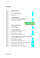
Contents 1 Introduction to STEP 7 1.1 What You Will Learn 1-1 1.2 Combining Hardware and Software 1-3 1.3 Basic Procedure Using STEP 7 1-4 1.4 Installing STEP 7 1-5 2 The SIMATIC Manager 2.1 Starting the SIMATIC Manager and Creating a Project 2-1 2.2 The Project Structure in the SIMATIC Manager and How to Call the Online Help 2-4 In Chapters 3 to 5, you create a simple program. 3 Programming with Symbols 3.1 Absolute Addresses 3-1 3.
Contents In Chapters 6 and 7, you configure the hardware and test your program. 6 Configuring the Central Rack 6.1 Configuring Hardware 7 Downloading and Debugging the Program 7.1 Establishing an Online Connection 7-1 7.2 Downloading the Program to the Programmable Controller 7-3 7.3 Testing the Program with Program Status 7-6 7.4 Testing the Program with the Variable Table 7-8 7.
1 Introduction to STEP 7 1.1 What You Will Learn Using practical exercises, we will show you how easy it is to program in Ladder Logic, Statement List, or Function Block Diagram with STEP 7. Detailed instructions in the individual chapters will show you step-by-step the many ways in which you can use STEP 7. Creating a Program with Binary Logic In Chapters 2 to 7, you will create a program with binary logic.
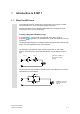
Introduction to STEP 7 The third binary logic operation is the memory element. The SR function reacts within a circuit diagram to certain voltage states and passes these on accordingly. Memory Element Key S S R Key R If key S is pressed, the bulb lights up and remains lit until key R is pressed.
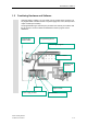
Introduction to STEP 7 1.2 Combining Hardware and Software Using the STEP 7 software, you can create your S7 program within a project. The S7 programmable controller consists of a power supply unit, a CPU, and input and output modules (I/O modules). The programmable logic controller (PLC) monitors and controls your machine with the S7 program. The I/O modules are addressed in the S7 program via the addresses.
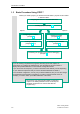
Introduction to STEP 7 1.3 Basic Procedure Using STEP 7 Before you create a project, you should know that STEP 7 projects can be created in different orders.
Introduction to STEP 7 1.4 Installing STEP 7 Regardless of whether you want to start with programming or configuring hardware, you first have to install STEP 7. If you are using a SIMATIC programming device, STEP 7 is already installed. When installing the STEP 7 software on a programming device or PC without a previously installed version of STEP 7, note the software and hardware requirements. You can find these in the Readme.wri on the STEP 7 CD under :\STEP 7 \Disk1.
Introduction to STEP 7 1-6 STEP 7 Getting Started C79000-P7076-C48-01
2 2.1 The SIMATIC Manager Starting the SIMATIC Manager and Creating a Project The SIMATIC Manager is the central window which becomes active when STEP 7 is started. The default setting starts the STEP 7 Wizard, which supports you when creating a STEP 7 project. The project structure is used to store and arrange all the data and programs in order.
The SIMATIC Manager For the "Getting Started" sample project, select CPU 314. The example has been created in such a way that you can actually select the CPU you have been supplied with at any time. The default setting for the MPI address is 2. Click Next to confirm the settings and move to the next dialog box. Every CPU has certain properties; for example, regarding its memory configuration or address areas. This is why you have to select the CPU before you start programming.
The SIMATIC Manager Double-click to select the suggested name in the "Project name" field and overwrite it with "Getting Started." Click Make to generate your new project according to the preview. When you click the Make button, the SIMATIC Manager will open with the window for the "Getting Started" project you have created. On the following pages, we will show you what the created files and folders are for and how you can work effectively with them.
The SIMATIC Manager 2.2 The Project Structure in the SIMATIC Manager and How to Call the Online Help As soon as the STEP 7 Wizard is closed, the SIMATIC Manager appears with the open project window "Getting Started." From here, you can start all the STEP 7 functions and windows.
The SIMATIC Manager Calling the Help on STEP 7 F1 Option 1: Place the cursor on any menu command and press the F1 key. The context-sensitive help for the selected menu command will appear. Option 2: Use the menu to open the STEP 7 online help. The contents page with various help topics appears in the left-hand pane and the selected topic is displayed in the right-hand pane. Navigate to the topic you want by clicking the + sign in the Contents list.
The SIMATIC Manager Navigating in the Project Structure The project you have just created is displayed with the selected S7 station and CPU. Click the + or – sign to open or close a folder. You can start other functions later on by clicking the symbols displayed in the right-hand pane. Click the S7 Program (1) folder. This contains all the necessary program components. You will use the Symbols component in Chapter 3 to give the addresses symbolic names.
3 Programming with Symbols 3.1 Absolute Addresses Every input and output has an absolute address predefined by the hardware configuration. This address is specified directly; that is, absolutely. The absolute address can be replaced by any symbolic name you choose.
Programming with Symbols 3.2 Symbolic Programming In the symbol table, you assign a symbolic name and the data type to all the absolute addresses which you will address later on in your program; for example, for input I 0.1 the symbolic name Key 1. These names apply to all parts of the program and are known as global variables. Using symbolic programming, you can considerably improve the legibility of the S7 program you have created.
Programming with Symbols Save the entries or changes you have made in the symbol table and close the window. Because there are lots of names for the entire "Getting Started" project, you can copy the symbol table to your "Getting Started" project in Section 4.1. Here you can see the symbol table for the S7 program in the "Getting Started" example for Statement List. Generally speaking, only one symbol table is created per S7 program, regardless of which programming language you have selected.
Programming with Symbols 3-4 STEP 7 Getting Started C79000-P7076-C48-01
4 Creating a Program in OB1 4.1 Opening the LAD/STL/FBD Program Window Choosing Ladder Logic, Statement List, or Function Block Diagram With STEP 7, you create S7 programs in the standard languages Ladder Logic (LAD), Statement List (STL), or Function Block Diagram (FBD). In practice, and for this chapter too, you must decide which language to use. Ladder Logic (LAD) Suitable for users from the electrical engineering industry, for example.
Creating a Program in OB1 Copying the Symbol Table and Opening OB1 If necessary, open your "Getting Started" project. To do this, click the Open button in the toolbar, select the "Getting Started" project you created, and confirm with OK.
Creating a Program in OB1 The LAD/STL/FBD Program Window All blocks are programmed in the LAD/STL/FBD program window. Here, you can see the view for Ladder Logic.
Creating a Program in OB1 4.2 Programming OB1 in Ladder Logic In the following section, you will program a series circuit, a parallel circuit, and the set / reset memory function in Ladder Logic (LAD). Programming a Series Circuit in Ladder Logic If necessary, set LAD as the programming language in the View menu. Click in the title area of OB1 and enter "Cyclically processed main program," for example. Select the current path for your first element.
Creating a Program in OB1 Click the ??.? sign and enter the symbolic name "Key_1" (in quotation marks). Alternatively, you can select the name from the displayed pull-down list. Confirm with Enter. Enter the symbolic name "Key_2" for the second normally open contact. Enter the name "Green_Light" for the coil. You have now programmed a complete series circuit. Save the block if there are no more symbols shown in red.
Creating a Program in OB1 Programming a Parallel Circuit in Ladder Logic Select Network 1. Insert a new network. Select the current path again. Insert a normally open contact and a coil. Select the vertical line of the current path. Insert a parallel branch. Add another normally open contact in the parallel branch. Close the branch (if necessary, select the lower arrow). The addresses are still missing in the parallel circuit.
Creating a Program in OB1 Programming a Memory Function in Ladder Logic Select Network 2 and insert another network. Select the current path again. Navigate in the Program Elements catalog under Bit Logic until you reach the SR element. Double-click to insert the element. Insert a normally open contact in front of each of the inputs S and R.
Creating a Program in OB1 4.3 Programming OB1 in Statement List In the following section, you will program an AND instruction, an OR instruction, and the memory instruction set/reset in Statement List (STL). Programming an AND Instruction in Statement List If necessary, set STL as the programming language in the View menu. Check whether symbolic representation is activated. Click in the title area of OB1 and enter "Cyclically processed main program," for example.
Creating a Program in OB1 In the same way, complete the AND instruction as shown. You have now programmed a complete AND instruction. Save the block if there are no more symbols shown in red. Symbols are indicated in red if, for example, they do not exist in the symbol table, or if there is a syntax error. Programming an OR Instruction in Statement List Select Network 1. Insert a new network and select the input area again.
Creating a Program in OB1 Programming a Memory Instruction in Statement List Select Network 2 and insert another network. In the first line, type the instruction A with the symbolic name "Automatic_On." Complete the memory instruction and save it. Close the block. If you want to see the difference between absolute and symbolic addressing, deactivate the menu command View > Display > Symbolic Representation.
Creating a Program in OB1 4.4 Programming OB1 in Function Block Diagram In the following section, you will program an AND function, an OR function, and a memory function in Function Block Diagram (FBD). Programming an AND Function in Function Block Diagram If necessary, set FBD as the programming language in the View menu. Click in the title area of OB1 and enter "Cyclically processed main program," for example. Select the input area for the AND function (below the comment field).
Creating a Program in OB1 Click on the ??.? sign and enter the symbolic name "Key_1" (in quotation marks). Alternatively, you can also select the name from the displayed pull-down list. Confirm with Enter. Enter the symbolic name "Key_2" for the second input. Enter the name "Green_Light" for the assignment. You have now programmed a complete AND function. If there are no more symbols shown in red, you can save the block.
Creating a Program in OB1 Programming an OR Function in Function Block Diagram Insert a new network. Select the input area again for the OR function. Insert an OR box (≥1) and an assignment (=). The addresses are still missing in the OR function. Proceed in the same way as for the AND function. Enter "Key_3" for the upper input, "Key_4" for the lower input, and "Red_Light" for the assignment. Save the block.
Creating a Program in OB1 Programming a Memory Function in Function Block Diagram Select Network 2 and insert another network. Select the input area again (below the comment field). Navigate in the Program Elements catalog under Bit Logic until you reach the SR element. Double-click to insert the element. "Automatic Mode" "Automatic on" Enter the following symbolic names for the SR element: Set "Automatic_On" Reset "Manual_On" Memory bit "Automatic_Mode" "Manual on" Save the block and close the window.
5 Creating a Program with Function Blocks and Data Blocks 5.1 Creating and Opening Function Blocks (FB) The function block (FB) is below the organization block in the program hierarchy. It contains a part of the program which can be called many times in OB1. All the formal parameters and static data of the function block are saved in a separate data block (DB), which is assigned to the function block.
Creating a Program with Function Blocks and Data Blocks In the "Properties – Function Block" dialog box, select the language in which you want to create the block, activate the check box "Multiple instance FB," and confirm the remaining settings with OK. The function block FB1 has been inserted in the Blocks folder. Double-click FB1 to open the LAD/STL/FBD program window. Depending on which programming language you have selected, continue reading in either Section 5.2 for Ladder Logic, Section 5.
Creating a Program with Function Blocks and Data Blocks 5.2 Programming FB1 in Ladder Logic We will now show you how to program a function block which can, for example, control and monitor a petrol or diesel engine using two different data blocks. All "engine-specific" signals are passed on as block parameters from the organization block to the function block and must therefore be listed in the variable declaration table as input and output parameters (declaration "in" and "out").
Creating a Program with Function Blocks and Data Blocks Only letters, numbers, and the underscore are permitted characters for the names of the block parameters in the variable declaration table. If all the columns required are not displayed in your variable details, you can display it via the shortcut menu command (via a right-mouse click).
Creating a Program with Function Blocks and Data Blocks Check whether symbolic representation is activated. Select the question marks and enter the corresponding names from the variable declaration table (the # sign is assigned automatically). Enter the symbolic name "Automatic_Mode" for the normally closed contact in the series circuit. Then save your program. Local block variables are indicated with a # sign and are only valid in the block. Global variables appear in quotation marks.
Creating a Program with Function Blocks and Data Blocks Programming Speed Monitoring Insert a new network and select the current path. Then navigate in the Program Elements catalog until you reach the Compare function and insert a CMP>=I. Also insert a coil in the current path. Select the question marks again and label the coil and the comparator with the names from the variable declaration table. Then save your program.
Creating a Program with Function Blocks and Data Blocks 5.3 Programming FB1 in Statement List We will now show you how to program a function block which can, for example, control and monitor a petrol or diesel engine using two different data blocks. All "engine-specific" signals are passed on as block parameters from the organization block to the function block and must therefore be listed in the variable declaration table as input and output parameters (declaration "in" and "out").
Creating a Program with Function Blocks and Data Blocks Only letters, numbers, and the underscore are permitted characters for the names of the block parameters in the variable declaration table. Programming an Engine to Switch On and Off Check whether symbolic representation is activated. Enter the corresponding instructions in Network 1. Local block variables are indicated with a # sign and are only valid in the block. Global variables appear in quotation marks.
Creating a Program with Function Blocks and Data Blocks Programming Speed Monitoring Insert a new network and enter the corresponding instructions. Then save your program. When is the engine switched on and off? When the variable #Switch_On has signal state "1" and the variable "Automatic_Mode" has signal state "0," the engine is switched on. This function is not enabled until "Automatic_Mode" is negated (normally closed contact).
Creating a Program with Function Blocks and Data Blocks 5.4 Programming FB1 in Function Block Diagram We will now show you how to program a function block which can, for example, control and monitor a petrol or diesel engine using two different data blocks. All "engine-specific" signals are passed on as block parameters from the organization block to the function block and must therefore be listed in the variable declaration table as input and output parameters (declaration "in" and "out").
Creating a Program with Function Blocks and Data Blocks Local block variables are indicated with a # sign and are only valid in the block. Global variables appear in quotation marks. These are defined in the symbol table and are valid for the entire program. Programming an Engine to Switch On and Off Insert an SR function in Network 1 using the Program Elements catalog (Bit Logic folder). Add an AND box at input S (Set), and an OR box at input R (Reset).
Creating a Program with Function Blocks and Data Blocks Click the ??.? sign and enter the corresponding names from the declaration table (the # sign is assigned automatically). Make sure that one input of the AND function is addressed with the symbolic name "Automatic_Mode." Negate the inputs "Automatic_Mode" and #Fault with the corresponding button from the toolbar. Then save your program. Local block variables are indicated with a # sign and are only valid in the block.
Creating a Program with Function Blocks and Data Blocks Programming Speed Monitoring Insert a new network and select the input area. Then navigate in the Program Elements catalog under you reach the Compare function, and insert a CMP>=I. Append an output assignment to the comparator and address the inputs with the names from the variable declaration table. Then save your program.
Creating a Program with Function Blocks and Data Blocks 5.5 Generating Instance Data Blocks and Changing Actual Values You have just programmed the function block FB1 ("Engine") and defined, among other things, the engine-specific parameters in the variable declaration table. In order for you to be able to program the call for the function block in OB1 later on, you must generate the corresponding data block. An instance data block (DB) is always assigned to a function block.
Creating a Program with Function Blocks and Data Blocks Confirm the subsequent dialog with Yes to assign parameters to the instance data blocks. Next enter the value "1500" for the petrol engine in the Actual Value column (in the row "Setpoint_Speed). You have now defined the maximum speed for this engine. Save DB1 and close the program window. In the same way as for DB1, generate another data block, DB2, for FB1. Now enter the actual value "1200" for the diesel engine.
Creating a Program with Function Blocks and Data Blocks 5.6 Programming a Block Call in Ladder Logic All the work you have done programming a function block is of no use unless you call this block in OB1. A data block is used for each function block call, and in this way, you can control both engines. OB1 Call FB1 "Engine" DB1 Petrol Engine Data DB2 Diesel Engine Data The SIMATIC Manager is open with your "Getting Started" project. Navigate to the Blocks folder and open OB1.
Creating a Program with Function Blocks and Data Blocks Double-click the data block Petrol. This block is then entered automatically in the input frame in quotation marks. Click the question marks and after entering a quotation mark address all the other parameters of the function block using the corresponding symbolic names in the pull-down list. The engine-specific input and output variables (declaration "in" and "out") are displayed in the FB "Engine.
Creating a Program with Function Blocks and Data Blocks Program the call for the function block "Engine" (FB1) with the data block "Diesel" (DB2) in a new network and use the corresponding addresses from the pull-down list. A signal "DE_xxx" is assigned to each of the variables for the diesel engine. Save your program and close the block.
Creating a Program with Function Blocks and Data Blocks 5.7 Programming a Block Call in Statement List All the work you have done programming a function block is of no use unless you call this block in OB1. A data block is used for each function block call, and in this way, you can control both engines. OB1 Call FB1 "Engine" DB1 Petrol Engine Data DB2 Diesel Engine Data The SIMATIC Manager is open with your "Getting Started" project. Navigate to the Blocks folder and open OB1.
Creating a Program with Function Blocks and Data Blocks Click the name Switch_On_PE. This is taken from the pull-down list and added automatically in quotation marks. Assign all the required addresses to the variables of the function block using the pull-down list. A signal "PE_xxx" is assigned to each of the variables for the petrol engine. Program the call for the function block "Engine" (FB1) with the data block "Diesel" (DB2) in a new network. Proceed in the same way as for the other call.
Creating a Program with Function Blocks and Data Blocks 5.8 Programming a Block Call in Function Block Diagram All the work you have done programming a function block is of no use unless you call this block in OB1. A data block is used for each function block call, and in this way, you can control both engines. OB1 Call FB1 "Engine" DB1 Petrol Engine Data DB2 Diesel Engine Data The SIMATIC Manager is open with your "Getting Started" project. Navigate to the Blocks folder and open OB1.
Creating a Program with Function Blocks and Data Blocks Double-click the data block Petrol. It is taken from the pull-down list and entered automatically in the input frame in quotation marks. Address all the other parameters of the function block using the corresponding symbolic names in the pull-down list. A signal "PE_xxx" is assigned to each of the variables for the petrol engine.
Creating a Program with Function Blocks and Data Blocks Program the call for the function block "Engine" (FB1) with the data block "Diesel" (DB2) in a new network and use the corresponding addresses from the pull-down list. A signal "DE_xxx" is assigned to each of the variables for the diesel engine. Save your program and close the block.
Creating a Program with Function Blocks and Data Blocks 5-24 STEP 7 Getting Started C79000-P7076-C48-01
6 Configuring the Central Rack 6.1 Configuring Hardware You can configure the hardware once you have created a project with a SIMATIC station. The project structure which was created with the STEP 7 Wizard in Section 2.1 meets all the requirements for this. The hardware is configured with STEP 7. These configuration data are transferred to the programmable controller later on "downloading" (see Chapter 7). The starting point is the open SIMATIC Manager together with the "Getting Started" project.
Configuring the Central Rack First you require a power supply module. Navigate in the catalog until you reach the PS307 2A and drag and drop this onto slot 1. Navigate until you find the input module (DI, Digital Input) SM321 DI32xDC24V and insert this in slot 4. Slot 3 remains empty. In the same way, insert the output module SM322 DO32xDC24V/0.5A in slot 5. In order to change the parameters (for example, address) of a module within a project, double-click the module.
7 Downloading and Debugging the Program 7.1 Establishing an Online Connection Using the supplied project "GS-LAD_Example" or the "Getting Started" project you have created and a simple test configuration, we will show you how to download the program to the programmable logic controller (PLC) and then debug it.
Downloading and Debugging the Program Configuring the Hardware To assemble a module on the rail, proceed in the order given below: • Attach the module onto the bus connector • Hang the module on the rail and swing it downwards • Screw the module in place • Assemble the remaining modules • Insert the key in the CPU once you have finished assembling all the modules. You can still carry out the test even if you are using different hardware to that shown in the diagram.
Downloading and Debugging the Program 7.2 Downloading the Program to the Programmable Controller You must have already established an online connextion in order tp download the program... ................................................................................................................ Applying Voltage Switch on the power supply using the ON/OFF switch. The diode "DC 5V" will light up on the CPU. Turn the operating mode switch to the STOP position (if not already in STOP).
Downloading and Debugging the Program Start the SIMATIC Manager and open the "Getting Started" project in the "Open" dialog box (if it is not already open). In addition to the "Getting Started Offline" window, open the "Getting Started ONLINE" window. The online or offline status is indicated by the different colored headers. Navigate in both windows to the Blocks folder. The offline window shows the situation on the programming device; the online window shows the situation on the CPU.
Downloading and Debugging the Program Switching on the CPU and Checking the Operating Mode Turn the operating mode switch to RUN-P. The green "RUN" LED lights up and the red "STOP" LED goes out. The CPU is ready for operation. When the green LED lights up, you can start testing the program. If the red LED remains lit, an error has occurred. You would then have to evaluate the diagnostic buffer in order to diagnose the error.
Downloading and Debugging the Program 7.3 Testing the Program with Program Status Using the program status function, you can test the program in a block. The requirement for this is that you have established an online connection to the CPU, the CPU is in RUN or RUN-P mode, and the program has been downloaded. Open OB1 in the project window "Getting Started ONLINE." The LAD/STL/FBD program window is opened. Activate the function Debug > Monitor.
Downloading and Debugging the Program I 0.1 Now press both keys in your test configuration. The diodes for input I 0.1 and I 0.2 light up on the input module. I 0.2 The diode for output Q 4.0 lights up on the output module. In the graphic programming languages Ladder Logic and Function Block Diagram, you can trace the test result by following the change in color in the programmed network. This color change shows that the result of logic operation is fulfilled up to this point.
Downloading and Debugging the Program 7.4 Testing the Program with the Variable Table You can test individual program variables by monitoring and modifying them. The requirement for this is that you have established an online connection to the CPU, the CPU is in RUN-P mode, and the program has been downloaded. As with testing with program status, you can monitor the inputs and outputs in Network 1 (series circuit or AND function) in the variable table.
Downloading and Debugging the Program At first, the variable table is empty. Enter the symbolic names or the addresses for the "Getting Started" example according to the illustration below. The remaining details will be added when you complete your entry with Enter. Change the status format of all the speed values to DEC (decimal) format. To do this, click the corresponding cell and select DEC format using the right mouse button. Save your variable table.
Downloading and Debugging the Program Monitoring Variables Click the Monitor Variables button in the toolbar. Press Key 1 and Key 2 in your test configuration and monitor the result in the variable table. The status values in the variable table will change from false to true. Modifying Variables Enter the value "1500" for the address MW2 in the Modify Value column and "1300" for the address MW4. Transfer the modify values to your CPU.
Downloading and Debugging the Program Following transfer, these values will be processed in your CPU. The result of the comparison becomes visible. Stop monitoring the variables (click the button in the toolbar again) and close the window. Acknowledge any queries with Yes or OK. Very large variable tables often cannot be displayed fully due to the limited screen space. If you have large variable tables, we recommend you create several tables for one S7 program using STEP 7.
Downloading and Debugging the Program 7.5 Evaluating the Diagnostic Buffer If, in an extreme case, the CPU goes into STOP while processing an S7 program, or if you cannot switch the CPU to RUN after you have downloaded the program, you can determine the cause of the error from the events listed in the diagnostic buffer. The requirement for this is that you have established an online connection to the CPU and the CPU is in STOP mode. First turn the operating mode switch on the CPU to STOP.
Downloading and Debugging the Program The "Module Information" window provides you with information on the properties and parameters of your CPU. Now select the "Diagnostic Buffer" tab to determine the cause of the STOP state. The "Open Block" button is disabled, because there was no error in the block in the "Getting Started" project. The latest event (number 1) is at the top of the list. The cause of the STOP state is displayed. Close all windows except for the SIMATIC Manager.
Downloading and Debugging the Program 7-14 STEP 7 Getting Started C79000-P7076-C48-01
8 Programming a Function 8.1 Creating and Opening Functions (FC) Functions, like function blocks, are below the organization block in the program hierarchy. In order for a function to be processed by the CPU, it must also be called in the block above it in the hierarchy. In contrast to the function block, however, no data block is necessary. With functions, the parameters are also listed in the variable declaration table, but static local data are not permitted.
Programming a Function Insert a Function (FC) from the pop-up menu. In the "Properties – Function" dialog box, accept the name FC1 and select the required programming language. Confirm the remaining default settings with OK. The function FC1 is added to the Blocks folder. Double-click to open FC1. In contrast to the function block, no static data can be defined in the variable declaration table for a function. The static data defined in a function block are retained when the block is closed.
Programming a Function 8.2 Programming Functions In this section, you will program a timer function in our example. The timer function enables a fan to switch on as soon as an engine is switched on (see Chapter 5), and the fan then continues running for four seconds after the engine is switched off (off-delay). As mentioned earlier, you must specify the input and output parameters of the function ("in" and "out" declaration) in the variable detail view. The LAD/STL/FBD program window is open.
Programming a Function Select the question marks, enter "#" and select the corresponding names. Set the delay time at input TV of S_OFFDT. Here, S5T#4s means that a constant has been defined with the data type S5Time#(S5T#), lasting four seconds (4s). Then save the function and close the window. The "#Timer_Function" is started with the input parameter "#Engine_On.
Programming a Function Programming the Timer Function in Function Block Diagram If you are programming in Function Block Diagram, select the input area below the network and enter the FBD program below for the timer function. Then save the function and close the window. In order for the timer function to be processed, you need to call the function in a block which is higher up in the block hierarchy (in our example, in OB1).
Programming a Function 8.3 Calling the Function in OB1 The call for the function FC1 is carried out in a similar way to the call for the function block in OB1. All the parameters of the function are supplied in OB1 with the corresponding addresses of the petrol or diesel engine. Since these addresses are not yet defined in the symbol table, the symbolic names of the addresses will now be added. An address is part of a STEP 7 statement and specifies what the processor should execute the instruction on.
Programming a Function Program the call for the function FC1 in Network 7 using the addresses for the diesel engine. You can do this in the same way as for the previous network (you have already added the addresses for the diesel engine to the symbol table). Save the block and then close the window. Activate the menu command View >Display > Symbol Information to view the information on individual addresses in each network.
Programming a Function Programming the Call in Statement List If you are programming in Statement List, select the input area below a new network and enter the STL statements shown here. Then save the call and close the window. Programming the Call in Function Block Diagram If you are programming in Function Block Diagram, select the input area below a new network and enter the FBD instructions shown below. Then save the call and close the window.
9 Programming a Shared Data Block 9.1 Creating and Opening Shared Data Blocks If there are not enough internal memory bits in a CPU to save all the data, you can store specific data in a shared data block. The data in a shared data block are available to every other block. An instance data block, on the other hand, is assigned to one specific function block, and its data are only available locally in this function block (see Section 5.5).
Programming a Shared Data Block Insert a Data Block (DB) from the pop-up menu. In the "Properties – Data Block" dialog box, accept all the default settings with OK. Use the "Help“ Button for further information. The data block DB3 has been added to the Blocks folder. Double-click to open DB3. Remember: In Section 5.5, you generated an instance data block by activating the option "Data block referencing a function block." In contrast, using "Data block" you create a shared data block.
Programming a Shared Data Block Assigning Symbols You can also assign symbolic names to data blocks. Open the Symbol Table and enter the symbolic name "S_Data" for the data block DB3. If you copied the symbol table from a sample project (zEn01_02_STEP7__STL_1-10, zEn01_06_STEP7__LAD_1-10 or zEn01_04_STEP7__FBD_1-10) to your "Getting Started" project in Chapter 4, you do not need to add any symbols now. Save the symbol table and close the "Symbol Editor" window. Also close the shared data block.
Programming a Shared Data Block 9-4 STEP 7 Getting Started C79000-P7076-C48-01
10 Programming a Multiple Instance 10.1 Creating and Opening a Higher-Level Function Block In Chapter 5 you created a program for controlling an engine with the function block "Engine" (FB1). When the function block FB1 was called in the organization block OB1, it used the data blocks "Petrol" (DB1) and "Diesel" (DB2). Each data block contained the different data for the engines (for example, #Setpoint_Speed).
Programming a Multiple Instance If you have worked through the "Getting Started" example in Chapters 1 to 7, open the "Getting Started" project. If not, open one of the following projects in the SIMATIC Manager: ZEn01_05_STEP7__LAD_1-9 for Ladder Logic, ZEn01_01_STEP7__STL_1-9 for Statement List ZEn01_03_STEP7__FBD_1-9 for Function Block Diagram. Navigate to the Blocks folder and open it. Click with the right mouse button in the right half of the window and insert a function block using the pop-up menu.
Programming a Multiple Instance 10.2 Programming FB10 To call FB1 as a "local instance" of FB10, in the variable detail view a static variable must be declared with a different name for each planned call of FB1. Here, the data type is FB1 ("Engine"). Declare / Define Variables FB10 is open in the LAD/STL/FBD program window. Transfer the declarations of the subsequent image to your variable detail view.
Programming a Multiple Instance Programming FB10 in Ladder Logic Insert the call "Petrol_Engine" as the multiple-instance block "Petrol_Engine" in Network 1. Then insert the required normally open contacts and complete the call with the symbolic names. The "Actual_Speed" for the engines is not taken from a memory bit (see Section 5.6 onwards), but from a shared data block (see Section 9.1). The general address assignment is as follows: "Data_Block".Address, for example: "S_Data".PE_Actual_Speed.
Programming a Multiple Instance Insert a new network and program a series circuit with the corresponding addresses. Then save your program and close the block. Use the respective temporary variables. You will recognize the temporary variables in the pull-down menu by the symbols displayed on the left. Then save your program and close the block.
Programming a Multiple Instance Programming FB10 in Function Block Diagram If you are programming in Function Block Diagram, select the input area under a new network and enter the FBD instructions below. Then save your program and close the block. To edit both calls for FB1 in FB10, FB10 must be called itself. Multiple instances can only be programmed for function blocks. Creating multiple instances for functions (FCs) is not possible.
Programming a Multiple Instance 10.3 Generating DB10 and Adapting the Actual Value The new data block DB10 will replace the data blocks DB1 and DB2. The data for the petrol engine and the diesel engine are stored in DB10 and will be required later for calling FB10 in OB1 (see "Calling FB1 in OB1" from Section 5.6 onwards). Create the data block DB10 in the Blocks folder of the "Getting Started" project in the SIMATIC Manager using the pop-up menu.
Programming a Multiple Instance Change the actual value of the diesel engine to "1300," save the block, and then close it. All the variables are now contained in the variable declaration table of DB10. In the first half, you can see the variables for calling the function block "Petrol_Engine" and in the second half the variables for calling the function block "Diesel_Engine" (see Section 5.5). The "internal" variables of FB1 retain their symbolic names; for example, "Switch_On.
Programming a Multiple Instance 10.4 Calling FB10 in OB1 The call for FB10 is made in OB1 in our example. This call represents the same function which you have learned while programming and calling FB1 in OB1 (see Section 5.6 onwards.). Using multiple instances, you can replace Networks 4 and 5 programmed from Section 5.6 onwards. Open OB1 in the project in which you have just programmed FB10. Defining Symbolic Names The LAD/STL/FBD program window is open.
Programming a Multiple Instance Complete the call below with the corresponding symbolic names. Delete the call for FB1 in OB1 (Networks 4 and 5 from Section 5.6 onwards), since we are now calling FB1 centrally via FB10. Then save your program and close the block. The output signal "Setpoint_Reached" for FB10 ("Engines") is passed on to the variable in the shared data block.
Programming a Multiple Instance Programming the Call in Function Block Diagram If you are programming in Function Block Diagram, select the input area under the new network and enter the FBD instructions below. To do this, use the FB Blocks > FB10 Engines in the Program Elements catalog. Delete the call for FB1 in OB1 (Networks 4 and 5 from Section 5.6 onwards), since we are now calling FB1 centrally via FB10. Then save your program and close the block.
Programming a Multiple Instance 10-12 STEP 7 Getting Started C79000-P7076-C48-01
11 Configuring the Distributed I/O 11.1 Configuring the Distributed I/O with PROFIBUS DP Automation systems with conventional configurations have the cable connections to the sensors and actuators inserted directly into the I/O modules of the central programmable logic controller. This often means a considerable amount of wiring is involved. Using a distributed configuration, you can considerably reduce the amount of wiring involved by placing the input and output modules close to the sensors and actuators.
Configuring the Distributed I/O Creating a New Project The starting point is the SIMATIC Manager. To make things easier to follow, close any open projects. Create a new project. Select the CPU 315-2DP in the corresponding dialog box (CPU with PROFIBUS-DP network). Now proceed in the same way as for Section 2.1 and assign the project the name "GS-DP" (Getting Started – Distributed I/O). If you want to create your own configuration at this point, specify your CPU now.
Configuring the Distributed I/O Configuring the Station Select the folder SIMATIC 300 Station and double-click Hardware. The "HW Config" window is opened (see Section 6.1). The CPU 315-2 DP already appears in the rack. If necessary, open the Hardware catalog using the menu command View > Hardware Catalog or the corresponding button in the toolbar. Drag and drop the power supply module PS307 2A into slot 1. In the same way, insert the I/O modules DI32xDC24V and DO32xDC24V/0.5A in slots 4 and 5.
Configuring the Distributed I/O Configuring the DP-Master System Select the DP master in slot 2.1 and insert a DP-master system. Apply the suggested address in the dialog box displayed. Select "PROFIBUS(1)" in the "Subnet" field and then apply your settings with OK. You can now move any objects which you place in the master system by dragging them with the left mouse button held down.
Configuring the Distributed I/O In the same way, drag and drop the module B-16DO onto the master system. The node address is automatically adapted in the dialog box. Confirm this entry with OK. Drag and drop the interface module IM153 onto the master system and confirm the node address again with OK. In our example, we are using the default node addresses. However, you can change these addresses at any time to meet your requirements. Select the ET200M in the network.
Configuring the Distributed I/O Changing the Node Address In our example, we do not need to change the node address. In practice, however, this is often necessary. Select the other nodes one after another and check the input and output addresses. The "Configuring Hardware" application has adapted all the addresses, so there are no double assignments. Let us imagine that you want to change the address of the ET200M: Select the ET200M and double-click DI32xDC24V (slot 4).
Configuring the Distributed I/O Finally, save and compile the distributed I/O configuration. Close the window. The menu command Save and Compile means that the configuration is automatically checked for consistency. If there are no errors, the system data are generated and can be downloaded to the programmable controller. With Save, you can save the configuration even if it contains errors. However, you cannot then download the configuration to the programmable controller.
Configuring the Distributed I/O Congratulations! You have worked through the Getting Started manual and learned the most important terms, procedures, and functions of STEP 7. Now you can get started on your first project. If, while working on future projects, you are looking for specific functions or have forgotten any of the operating instructions in STEP 7, you can use our comprehensive Help on STEP 7.
Appendix A Overview of the Sample Projects for the Getting Started Manual • ZEn01_02_STEP7__STL_1-10: The programmed Chapters 1 to 10 including the symbol table in the STL programming language. • ZEn01_01_STEP7__STL_1-9: The programmed Chapters 1 to 9 including the symbol table in the STL programming language. • ZEn01_06_STEP7__LAD_1-10: The programmed Chapters 1 to 10 including the symbol table in the LAD programming language.
Appendix A A-2 STEP 7 Getting Started C79000-P7076-C48-01
Index A Absolute address ................................ 3-1 Actual values changing ........................................... 5-14 AND function .......................................... 1-1 Applying voltage ..................................... 7-3 B Block call in function block diagram ..... 5-21 Block call in ladder logic ....................... 5-16 Block call in statement list .................... 5-19 C Calling the function................................. 8-6 Calling the Help ...................
Index M Modifying variables............................... 7-10 Module information, query.................... 7-12 Monitoring variables ............................. 7-10 Multiple instance, programming ........... 10-1 N Node addresses, changing................... 11-6 O Online connection, establishing.............. 7-1 Opening function blocks ......................... 5-1 Opening functions .................................. 8-1 Opening shared data blocks................... 9-1 Operating Mode, checking .