
Datasheet

Pressure Measurement
Transmitters for basic requirements
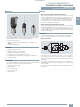
SITRANS P210
for gauge pressure
2/11
Siemens FI 01 · 2012
2
■
Overview
The pressure transmitter SITRANS P210 measures the gauge
pressure of liquids, gases and vapors.
• Stainless steal measuring cell
• Measuring ranges 100 to 600 mbar (1.45 to 8.7 psi) relative
• For low-pressure applications
■
Benefits
• High measuring accuracy
• Rugged stainless steel enclosure
• High overload withstand capability
• For aggressive and non-aggressive media
• For measuring the pressure of liquids, gases and vapors
• Compact design
■
Application
The pressure transmitter SITRANS P210 for gauge pressure is
used in the following industrial areas:
• Mechanical engineering
• Shipbuilding
• Power engineering
• Chemical industry
• Water supply
■
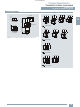
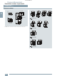
Design
Device structure without explosion protection
The pressure transmitter consists of a piezoresistive measuring
cell with a diaphragm installed in a stainless steel enclosure. It
can be used with a connector per EN 175301-803-A (IP65), a
round plug M12 (IP67), a cable (IP67) or a cable quick screw
connection (IP67) connected electrically. The output signal is
between 4 and 20 mA or 0 and 10 V.
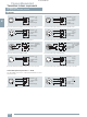
Device structure with explosion protection
The pressure transmitter consists of a piezoresistive measuring
cell with a diaphragm installed in a stainless steel enclosure. It
can be used with a connector per EN 175301-803-A (IP65) or a
round plug M12 (IP67) connected electrically. The output signal
is between 4 and 20 mA.
■
Function
The pressure transmitter measures the gauge pressure of liquids
and gases as well as the level of liquids.
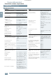
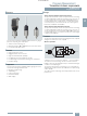
Mode of operation
SITRANS P210 pressure transmitters (7MF1566-...), functional diagram
The stainless steel measuring cell has a thin-film resistance
bridge to which the operating pressure p is transmitted through
a stainless steel diaphragm.
The voltage output from the measuring cell is converted by an
amplifier into an output current of 4 to 20 mA or an output voltage
of 0 to 10 V DC.
The output current and voltage are linearly proportional to the in-
put pressure.
U
const.
U
I
p
I
0
, U
B
FI01_2012_en_kap02.book Seite 11 Donnerstag, 17. November 2011 4:31 16
© Siemens AG 2011
© Siemens AG 2011