
Data Sheet for Product

Technical Instructions D Room Thermostat Direct Acting
Document Number 155-072P25
March 27, 2009
Page 2 Siemens Industry, Inc.
Specifications
Operating
Range 60°F to 85°F (15°C to 30°C)
Sensitivity 2-1/4 psi/°F (27.0 kPa/°C)
Normal supply pressure 18 psi (124 kPa)
Maximum supply pressure 30 psi (206 kPa)
Maximum ambient temperature 110°F (43°C)
Temperature response 1/2°F (0.3°C)
Weight 3 lbs (1.4 kg)
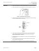
Dimensions See Figure 6
Operation
A direct acting thermostat will increase control pressure with a rise in temperature and
decrease control pressure with a drop in temperature. The thermostat may be
controlling a mixing damper supplying hot or cold air to a room. The exhaust valve
chamber is connected by a branch line directly to the damper motor controlling the
position of the hot and cold blades. See Figure 1.
When room temperature increases, the thermostat increases the control pressure to the
motor to close the hot blade and open the cold blade. Conversely, with a drop in room
temperature, the thermostat reduces the control pressure to close the cold blade and
open the hot blade. Due to the gradual action of the Powers Type D Thermostat, the hot
and cold blades may be positioned in an intermediate position to satisfy the room’s
needs.
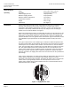
The Type D Thermostat is a force-balance type of instrument. When temperature rises,
the vapor pressure within the thermostatic discs increases and overcomes the pressure
exerted by the air in the exhaust valve chamber. The first action is to seat the exhaust
valve. Then the supply valve is moved from its seat and allows air to flow into the return
line. This unique feature prevents the constant waste of air. The air pressure in the
exhaust valve chamber exerts a feedback pressure in opposition to the vapor pressure
in the disc. Therefore, whenever there is sufficient air pressure to balance the vapor
pressure of the discs, the supply valve returns to its seat and no more air is permitted to
pass through.
Upon a drop in temperature, the vapor pressure within the thermostatic discs decreases
and the greater air pressure in the exhaust valve chamber results in a reverse
movement of the exhaust valve assembly. This allows the supply valve to close and the
exhaust valve to open gradually to reduce the control pressure. The force in the
exhaust valve chamber always tends to balance the force of the thermostatic discs to
maintain desired room conditions.
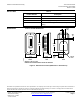
CONTROL
PRESSURE
SUPPLY
PRESSURE
SUPPLY
VALVE
FEEDBACK
DIAPHRAGM
EXHAUST
VALVE
TH0517R1
Figure 1. Supply Exhaust Valve.