
Data Sheet for Product

Technical Instructions D Room Thermostat Direct Acting
Document Number 155-072P25
March 27, 2009
Page 4 Siemens Industry, Inc.
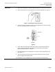
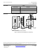
Construction
30
29
25
37
15
16
24
33
34
1
2
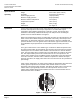
To remove, use
Key No. 856-055
28
27
26
1720
19
18
23
21
22
32
31
35
TH0514R1
Table 2. Parts List.
Item No. Description Part Number
1. Screen Filte
r
2. Terminal Gasket
3. Supply Valve Cap Gasket
4. Supply Valve Spring
5. Supply Valve Stem
6. Supply Valve Gasket
7. Supply Valve Body
8. Exhaust Valve Stem
9. Exhaust Valve Spring
10. Exhaust Valve Body
11. Exhaust Valve Diaphragm
12. Exhaust Valve Diaphragm
Plate
*13. Exhaust Valve Nut
Kit Number
832-164
*13. Exhaust Valve Nut
(For 832-1260)
830-015
14. Supply Valve Cap 833-013
15. Base Plate Assembl
y
181-091
16. Motor Disc Assembly 934-007
17. Test Plug 833-009
*Order extra 830-015C in excess of 832-164 kit for repair of
832-1260 thermostat.
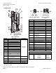
12
8
13
11
10
9
TH0516R1
Figure 4. Supply Valve.
14
7
6
5
43
TH0515R1
Figure 5. Exhaust
Valve.
Item Description Part
18. Lever Assembl
y
—
19. Self-locking Pivot Pin
—
20. Test Valve Body 833-008
21. Dial 833-010
22. Dial Scre
w
181-021
23. Scre
w
—
24. Diaphragm Ring 934-011
25. Frame
—
26. Dial Pinion 181-064
27. Lever Nut 833-067
28. Adjustment Screw
(For 832-1260)
833-075
28. Adjustment Screw
(For all others)
833-017B
29. Return Spring 221-054
30. Cove
r
See Table 3
31. Knob (Friction) 833-033
31. Adjustment Knob (For 832) 833-080
32. Set Screw (For 832-1260
Only
034-351
33. Terminal Head 832-159
34. Filter Disc
—
35. Scre
w
030-042
36. Adjustment Key (Not Shown) 856-055
37. Scre
w
856-014
Table 3. (Replacement Covers)
30. For Thermostat Number Cover
832-0120 856-036
832-0490 856-046**
832-1260 856-044
832-0500 856-044
**Two 856-014 screws required with this cover.
Replacement Kit No. 832-040 consists of D thermostat, less cover and base.