
User Manual


11
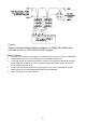
Figure 7.2
Isolated Installation/Wiring Diagram for ABHW-4B Audible Base Powered by
NAC of FC2025/FC2050/FV2025/FV2050 and FC922/FC924/FV922/FV924
Figure 7.2 Notes:
1. The NAC circuit shown in the diagram is the active state at terminal 1 and 2 of ABHW-4B.
2. ABHW-4B terminals 5-6-7 are polarity sensitive. Isolated wiring shown.
3. The wiring at NAC of FC2025/FC2050/FV2025/FV2050 and FC922/FC924/FV922/FV924
shown in the diagram for ABHW-4B is Style Z (Class A) (no EOL needed). If Style Y (Class
B) wiring used at NAC output, EOL (2.4 K, 0.5 W resistor) must be used.
4. For the max load current and max cable resistance, refer to the specifications of FC2025/FC2050
/FV2025/FV2050 and FC922/FC924/FV922/FV924.
5. NAC circuit does not provide isolation.