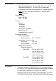
Installation Instructions Model ABHW-4S Intelligent Audible Base for Sleeping Area with 520Hz Low Frequency Sounder Introduction The Model ABHW-4S audible base from Siemens Industry, Inc. is an intelligent supervised base which is designed for use in sleeping areas. The base generates a 520 Hz square wave audio signal complying with the latest NFPA 72 standard and is UL/ULC listed. It provides six selectable tone patterns, two volume levels when used with compatible fire detectors and control panels.
Specifications Physical Specifications: Operating temperature: 32 °F ~ 120 °F (0 °C ~ 49 °C) Operating humidity:10 ~ 95%RH (Non Condensing) Compatible electrical mounting boxes: 4” square gang box ONLY with 2.
PAD-3/PAD-4/PAD-5 (refer to Figure 1), ZIC-4A (FireFinder- Configuration Important! XLS/Desigo Fire Safety Modular/Cerberus PRO Modular zone indicating card (NAC), refer to Figure 3), PAD-3/ PAD4/PAD-5 (Figure 4), or a 24 VDC NAC circuit such as FC2005/ FC901 (Refer to Figure 5.1) or NAC circuit such as FC2025/FC2050/FV2025/FV2050, FC922/FC924/FV922/ FV924 (Refer to Figure 5.2). 2. The alarm current of ABHW-4S CANNOT be energized by a 24 V FWR power supply. 3.
Detector wiring (Refer to Figures 7 and 8) Audible base Model ABHW-4S should be interconnected as shown in the Installation/ Wiring Diagrams and wired to the specific system modules and control panels following the appropriate instructions.
between 4 and 6 inches from the ceiling. If questions arise regarding detector placement, it is extremely important that the drawings provided or approved by Siemens Industry, Inc., or by its authorized distributors be followed! The detector placements shown on these drawings were chosen after a careful evaluation of all facets of protecting the area. Environmental factors such as air current, temperature, humidity, air pressure, and the nature of the fire load are carefully considered.
Compatible remote lamps (table 3): Model RL-HW RL-HC Siemens Part # 500-033310 500-033230 Doc.
Figure 1 and 2 Notes: 1. 2. 3. 4. 5. 6. RPR-1 remote relay and HTRI are used for 24 VDC power supervision. 24 VDC wire open will cause trouble reported by HTRI. Refer to Installation Instruction of RPR-1 (315-096055). ABHW-4S terminals 5-6 are polarity insensitive. Line 1 and Line 2 can be either line of device loop. EOL device of HTRI: 3.6 K, 1/4 W resistor, P/N 140-820185. EOL device of HTRI: 470 Ohm, 1/4 W resistor, P/N 140-820164. EOL device of XTRI: 470 Ohm, 1% 1/2 W Resistor, P/N A5Q00073045.
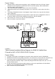
Figure 3 Notes: 1. 2. 3. 4. 5. 6. 7. Polarity shown in active state at terminals 1 and 2 of ABHW-4S and 1-4 of ZIC-4A. Proper polarity must be maintained or audible base will not operate properly. Each audible base must be tested to verify operation. Tone selection (Refer to page 12, Note 4, for more information). ABHW-4S terminals 5-6 are polarity insensitive. Line 1 and Line 2 can be either line of the loop. The wiring of ABHW-4S shown in the diagram is Style Z (Class A).
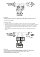
Figure 5.1 Installation/Wiring Diagram for ABHW-4S Audible Base Powered by NAC of FC2005/FC901 system Figure 5.1 Notes: 1. The NAC circuit shown in the diagram is the active state at terminal 1 and 2 of ABHW-4S. 2. ABHW-4S terminals 5-6 are polarity insensitive. Line 1 and Line 2 can be either line of device loop. 3. The wiring at NAC of FC2005/FC901 shown in the diagram for ABHW-4S is Style Z (Class A) (no EOL needed). If Style Y (Class B) wiring used at NAC output, EOL (24 K, 0.5 W resistor) must be used.
Figure 5.2 Notes: 1. The NAC circuit shown in the diagram is the active state at terminal 1 and 2 of ABHW-4S. 2. ABHW-4S terminals 5-6 are polarity insensitive. Line 1 and Line 2 can be either line of device loop. 3. The wiring at NAC of FC2025/FC2050/FV2025/FV2050 and FC922/FC924/FV922/FV924 shown in the diagram for ABHW-4S is Style Z (Class A) (no EOL needed). If Style Y (Class B) wiring used at NAC output, EOL (2.4 K, 0.5 W resistor) must be used. 4.
TO NEXT ABHW-4B, DB-11, DB-3S or DB-X3RS LINE 1 LINE 2 REMOTE LAMP See table 3 TB3 TB1 TB2 RLH LINE 1 LINE 2 FROM DLC LOOP OF FIREFINDER-XLS SYSTEM FC2005 / FC901 SYSTEM FC2025/FC2050/FV2025/FV2050 SYSTEM FC922/FC924/FV922/FV924 SYSTEM Figure 7 ABHW-4S Audible Base Terminal Blocks (only for FDO421, FDOT421, FDT421, FDOOT441, FDOOTC441, OP921, OH921, HI921, OOH941, HFPO-11, SFPO-11, and OOHC941 detectors.
ALARM LED LOCATION WITH DETECTOR INSTALLED IN BASE BASE MOUNTING HOLES Figure 8 Positioning the Alarm LED NOTES: 1. When installing FD-UL detectors in a FireFinder-XLS panel, use the following panel versions • PMI ver 10.02 or later • Zeus ver 10.02 or later • DLC ver 06.01 or later 2. ABHW-4S alarm current can ONLY be powered from auxiliary power; device loop power is used for the control circuits in ABHW-4S. 3.
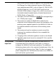
Cyber security disclaimer Siemens provides a portfolio of products, solutions, systems and services that includes security functions that support the secure operation of plants, systems, machines and networks. In the field of Building Technologies, this includes building automation and control, fire safety, security management as well as physical security systems.
Siemens Industry, Inc. Smart Infrastructure Florham Park, NJ Siemens Canada, Ltd.