
User Manual


3
zone indicating card (NAC), refer to Figure 2), PAD-3 or
PAD-4 (Figure 3),or a 24VDC NAC circuit such as FC2005/
FC901 (Refer to Figure 4.1) or NAC circuit such as
FC2025/FC2050/FV2025/FV2050, FC922/FC924/FV922/
FV924 (Refer to Figure 4.2).
2. The alarm current of ABHW-4S CAN’T be energized by a
24V FWR power supply.
3. The maximum number of ABHW-4S is related to the
maximum current rating and the power line resistance of the
auxiliary power supplies applied on the ABHW-4S. Refer to
the related installation instructions of the auxiliary power
supply.
4. The maximum loop line resistance cannot exceed the
maximum line resistance defined in the compatible fire
control panels.
5. T-tapping of the notification appliance circuit is not allowed.
6. The NAC output must be set to a steady DC if it is used for
ABHW-4S.
Configuration
Important!
The ABHW-4S must be configured by the panel when it is
connected with FD-UL detectors (see table 1). Failure to
configure the ABHW-4S will cause problems. For additional
information please refer to the manual of related panel. Also for
use with H-Series detectors (see table 2) it does not require
panel configuration as it will function the same as an ADBH-11
which will not be synchronized.
Detector
wiring
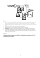
(Refer to Figure 6 & 7) Audible base Model ABHW-4S should
be interconnected as shown in the Installation/ Wiring
Diagrams
and wired to the specific system modules and control panels
following the appropriate instructions. For operation with
FireFinder-XLS, FC2005/FC901, FC2025/FC2050/FV2025/
FV2050, FC922/FC924/FV922/FV924 system, note any
limitations on the number of audible bases permitted on each
notification appliance circuit or 24VDC regulated power supply,
depending on the total cable resistance and total load of each
circuit. (See ELECTRICAL RATINGS section.)