
User Manual


4
Detector
mounting
The detector base comes from the factory prewired. All
signaling and initiating circuits are connected directly to the
back of the ABHW-4S audible base using the four position
terminal blocks.
Base
mounting
1. Route all wires out from the outlet box.
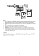
2. When the alarm LED viewing is critical, position the LED
mark on the base in the intended direction (Refer to Figure
7).
3. Make connections directly to the audible base terminals
located on the back of the base. Refer to the related
Installation/Wiring diagram.
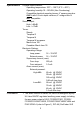
4. After all bases are installed, check loop continuity. For
ABHW-4S loop continuity check, refer to the DPU or SDPU
Manual, “Testing a FireFinder-XLS Loop”.
5. If loop continuity is acceptable, proceed with detector head
installation.
Detector
placement
Even though no specific spacing are allocated to the detectors
used with this base, use 30 foot center spacing (900 sq ft), as
referred to in NFPA Standard 72 National Fire Alarm Code
and CAN/ULC-S524, as a guide or starting point, if practical,
in a detector installation layout. This spacing is based on ideal
conditions—smooth ceiling, no air movement, and no physical
obstructions.
In all installations (except in special circumstances like
computer room under floors), locate the detector on the
ceiling, a minimum of 6 inches from a side wall, or on a wall,
between 4 and 6 inches from the ceiling.
If questions arise regarding detector placement, it is extremely
important that the drawings provided or approved by Siemens
Industry, Inc., or by its authorized distributors be followed! The
detector placements shown on these drawings were chosen
after a careful evaluation of all facets of protecting the area.
Environmental factors such as air current, temperature,
humidity, air pressure, and the nature of the fire load are
carefully considered. Special consideration is given to room or
area configuration and the type of ceiling (sloped or flat,
smooth or beamed). Siemens Industry, Inc.'s extensive