
User Manual


8
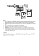
Note:
1. The NAC circuit shown in the diagram is the active state at terminal 1 and 2 of ABHW-4S.
2. ABHW-4S terminals 5-6 are polarity insensitive. Line 1 and Line 2 can be either line of device loop.
3. The wiring at NAC of PAD-3/PAD-4 shown in the diagram for ABHW-4S is Style Z (Class A)
(No EOL needed). If Style Y (Class B) wiring used at NAC output, EOL (24K, 0.5W resistor)
must be used.
4. For the max load current and max cable resistance, refer to the specifications of PAD-3/PAD-4,
P/N: 315-099082/315-050217.
Figure 3
Installation/Wiring Diagram for ABHW-4S Audible Base Powered by NAC of
PAD-3/PAD-4 System
Note:
1. The NAC circuit shown in the diagram is the active state at terminal 1 and 2 of ABHW-4S.
2. ABHW-4S terminals 5-6 are polarity insensitive. Line 1 and Line 2 can be either line of device loop.
3. The wiring at NAC of FC2005/FC901 shown in the diagram for ABHW-4S is Style Z (Class A)
(no EOL needed). If Style Y (Class B) wiring used at NAC output, EOL (24K, 0.5W resistor)
must be used.
4. For the max load current and max cable resistance, refer to the specifications of FC2005 /
FC901.
Figure 4.1
Installation/Wiring Diagram for ABHW-4S Audible Base Powered by NAC of
FC2005/FC901 system