Switch Disconnectors and Fuses 7/2 Introduction SENTRIC switch disconnectors 7/4 7/5 7/7 7/8 7/10 SENTRIC LD main control and EMERGENCY-STOP switches from 16 A to 125 A General data Front mounting Mounting in distribution boards Molded-plastic enclosures Accessories 7/12 7/14 7/15 7/16 SENTRIC K switch disconnectors from 63 A to 1000 A General data Base mounting Molded-plastic enclosures Accessories 7/17 7/20 7/21 SENTRIC NP fuse switch disconnectors General data For power distribution Accessories
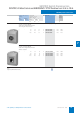
Switch Disconnectors and Fuses Introduction ■ Overview Type 3LD20 3LD21 3LD22 3LD25 3LD27 3LD28 SENTRIC LD main control and EMERGENCY-STOP switches from 16 A to 125 A 7 Rated uninterrupted current IU at 35 °C ambient temperature A 16 25 32 63 100 125 Rated operating voltage Ue V 690 690 690 690 690 690 AC-3 motor load switch operational switching of individual motors at 220 ... 240 V kW at 380 ... 440 V kW at 660/690 V kW 3.0 5.5 5.5 4.0 7.5 7.5 5.5 9.5 9.5 11.0 18.5 15.0 18.
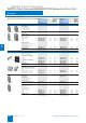
Switch Disconnectors and Fuses Introduction Type 3NP 3K SENTRIC Rated uninterrupted current IU at 35 °C ambient temperature A 160 ... 630 63 ...
SENTRIC Switch Disconnectors SENTRIC LD Main Control and EMERGENCY STOP Switches from 16 A to 125 A General data ■ Technical specifications Standards DIN VDE 0660, IEC 60947 Switch Type Number of contacts 7 3LD2 0 3LD2 1 3LD2 2 3LD2 5 3LD2 7 3LD2 8 3/4 3/4 3/4 3/4 3/4 3/4 Rated insulation voltage Ui Rated operating voltage Ue Rated frequency Rated impulse withstand voltage Uimp V AC V Hz kV 690 690 50 ... 60 6 690 690 50 ... 60 6 690 690 50 ...
SENTRIC Switch Disconnectors SENTRIC LD Main Control and EMERGENCY STOP Switches from 16 A to 125 A Front mounting ■ Area of application The SENTRIC 3LD2 switches are used for switching main control and auxiliary circuits, but they are also implemented for switching three-phase induction motors and other loads for maintenance and repair. They can be used as • On-Off switches, • EMERCENCY-STOP switches and • Main control switches according to EN 60204-1.
SENTRIC Switch Disconnectors SENTRIC LD Main Control and EMERGENCY STOP Switches from 16 A to 125 A Front mounting Number and version Rated data of the contacts at 50 Hz ... 60 Hz 380 V ... 440 V Main contacts Auxiliary contacts P/ P/ AC-3 AC23A Iu kW A kW DT PS* Order No. Weight per PU approx. kg Main control and EMERGENCY-STOP switch with rotary operating mechanism • IP65 degree of protection at the front 6 – 3LD2 103-3VK53 7.5 9.5 25 A 3LD2 103–3VK.. 1 unit 0.380 9.5 11.
SENTRIC Switch Disconnectors SENTRIC LD Main Control and EMERGENCY STOP Switches from 16 A to 125 A Mounting in distribution boards Number and version Rated data of contacts at 50 Hz ... 60 Hz 380 V ... 440 V Main contacts Auxiliary contacts P/ AC-23A Iu kW A DT PS* Order No. Weight per PU approx. kg ON/OFF and EMERGENCY-STOP switches with masking plate and selector switch • For mounting in a distribution board • For screw-fixing and snapping onto a 35 mm rail • Lockable in 0 position with max.
SENTRIC Switch Disconnectors SENTRIC LD Main Control and EMERGENCY STOP Switches from 16 A to 125 A Molded-plastic enclosures Number and version Rated data of contacts at 50 Hz ... 60 Hz 380 V ... 440 V Main contacts Auxiliary contacts P/ AC-23A Iu kW A DT PS* Order No. Weight per PU approx. kg Main control and EMERGENCY-STOP switches • With N or PE/ground terminal • Heavy-gauge threaded joints • Lockable in 0 position with max.
SENTRIC Switch Disconnectors SENTRIC LD Main Control and EMERGENCY STOP Switches from 16 A to 125 A Molded-plastic enclosures Number and version of contacts Rated data at 50 Hz ... 60 Hz 380 V ... 440 V Main contacts P/ AC-3 P/ AC-23A Iu kW kW A Auxiliary contacts DT PS* Order No. Weight per PU approx. kg Main control and EMERGENCY-STOP switches with rotary operating mechanism • metric screwed glands • With N or PE/ground terminals • IP65 degree of protection 6 – 7.5 9.
SENTRIC Switch Disconnectors SENTRIC LD Main Control and EMERGENCY STOP Switches from 16 A to 125 A Accessories ■ Selection and ordering data DT 3LD2 0 PS* Order No. Weight per PU approx. DT kg 3LD2 1 and 3LD2 2 PS* Order No. Weight per PU approx. kg For front mounting 4th contact (N conductor) for front mounting leading switch-on, delayed switch-off 3LD9 2.0-0B 3LD9 2.0-3B – } 3LD9 220–0B 1 unit 0.039 } 3LD9 200–2B 1 unit 0.030 } 3LD9 220–2B 1 unit 0.
SENTRIC Switch Disconnectors SENTRIC LD Main Control and EMERGENCY STOP Switches from 16 A to 125 A Accessories DT 3LD2 5 PS* Weight per PU approx. DT 3LD2 7 and 3LD2 8 Order No. PS* Weight per PU approx. Order No. For mounting on the front 3LD9 2.0-0B 3LD9 2.0-3B 3LD9 2.0-2B 3LD9 2.0-5B 4th contact (N conductor) for front mounting leading switch-on, delayed switch-off } 3LD9 250–0B 1 unit 0.079 } 3LD9 280–0B 1 unit 0.101 N or PE/ground terminal continuous } 3LD9 250–2B 1 unit 0.
SENTRIC Switch Disconnectors SENTRIC K Switch Disconnectors from 63 A to 1000 A General data ■ Technical specifications IEC 60947-1, IEC 60947-3, VDE 0660 Part 107 Standards 3KA50 3KA51 3KA52 3KA53 1) 3KA55 3KA571) 3KA58 A 63 80 125 160 250 400 6303) Type Rated uninterrupted current Iu A 63 80 125 160 250 400 630 3) Rated insulation voltage Ui V 690 690 1000 1000 1000 1000 1000 Rated impulse withstand voltageUimp kV 6 6 8 8 8 8 8 Rated operating voltage Ue AC 50
SENTRIC Switch Disconnectors SENTRIC K Switch Disconnectors from 63 A to 1000 A General data IEC 60947-1, IEC 60947-3, VDE 0660 Part 107 Standards 3KA50 3KA51 3KA52 3KA531) 3KA55 3KA571) 3KA58 Mechanical endurance operations 15000 15000 15000 15000 12000 12000 12000 Required operating torque Nm 3 3 7.5 7.
SENTRIC Switch Disconnectors SENTRIC K Switch Disconnectors from 63 A to 1000 A Base mounting ■ Area of application SENTRIC KA switch disconnectors are implemented as main control switches and EMERGENCY-STOP switches for normal switching duty and isolation of main circuits and auxiliary circuits. Another area of application is the switching of three-phase induction motors and other loads for maintenance and repair work.
SENTRIC Switch Disconnectors SENTRIC K Switch Disconnectors from 63 A to 1000 A Molded-plastic enclosures ■ Benefits ■ Area of application • Lockable with 3 padlocks • Generous terminal compartment • IP65 degree of protection • Maintenance-free • Easy to install. Our master and EMERCENCY-STOP switches provide absolute safety, even during maintenance and repair work. All-round safety for people and machines.
SENTRIC Switch Disconnectors SENTRIC K Switch Disconnectors from 63 A to 1000 A Accessories ■ Selection and ordering data DT 3KA50 30/ 3KA51 30 PS* Order No. Terminal cover (1 set = 6 units) for 3-pole devices 3KX3 552–3DA01 8UC62 12–1BB20 7 3KX3 516-1AA } 3KX3 552–3DA01 Weight per PU approx. DT kg 1 set 3KA50 40/ 3KA51 40/ 3KA52/ 3KA53 PS* Order No. 0.077 } } 3KA52 3KX3 552–3DA01 3KA53 3KX3 553–3DA01 Weight per PU approx. kg 1 set 0.077 1 set 0.147 1 set 0.
SENTRIC NP Fuse Switch Disconnectors General data ■ Area of application ■ Design SENTRIC NP fuse switch disconnectors are switching devices for the occasional manual connection and disconnection of loads and distribution boards. They are designed to connect the specified rated nominal current (including a specified overload), to carry it and to disconnect it. SENTRIC NP fuse switch disconnectors are used to isolate all poles of downstream electrical loads safely under load conditions.
SENTRIC NP Fuse Switch Disconnectors General data ■ Technical specifications Standards IEC 60947-1, IEC 60947-3, VDE 0660 Part 107 Type 3NP40 1 3NP40 7 3NP42 7 3NP43 7 3NP44 7 Rated uninterrupted current Iu For fuse links acc.
SENTRIC NP Fuse Switch Disconnectors General data Standards IEC 60 947-1, IEC 60 947-3, VDE 0660 Part 107 Type 3NP40 1 3NP40 7 3NP42 7 3NP43 7 3NP44 7 Capacitor switching capacity at AC 400 V Capacitor power Rated current In kvar A 50 72 50 72 – – – – – – at AC 525 V Capacitor power Rated current In kvar A 50 55 50 55 – – – – – – Permissible ambient temperature °C –25 ... +551) for operation, –50 ...
SENTRIC NP Fuse Switch Disconnectors For power distribution ■ Selection and ordering data Rated Conductor connections (on both sides) uninter- Connection For conductor rupted cross-section current Iu mm2 A For fuse For isolat- DT links to ing links2) 1) DIN 43620 Degree of protection IP00, without fuse links, without isolating links, with terminal screws Size Order No. PS* Weight per unit/ set/ meter appr.
SENTRIC NP Fuse Switch Disconnectors Accessories ■ Selection and ordering data For fuse switch dis- Version connectors DT Order No. PS* Weight per unit/ set/ meter approx. kg Quick fitting retaining plate between 2 rails to EN 50022 and EN 50023 3NY1 995 B 3NY1 995 1 unit 0.135 B 3NY7 322 1 unit 0.249 } 3NY7 101 1 set 0.065 3NP42 7 } 3NY7 121 1 set 0.220 3NP43 3NP44 } } 3NY7 131 3NY7 141 1 set 1 set 0.221 0.
SENTRIC KL Switch Disconnectors with Fuses General data ■ Area of application SENTRIC KL switch disconnectors with fuses protect against overload and short-circuits as main control and EMERGENCYSTOP switches of switchpanels, distribution boards, power supply and motor feeders. In conjunction with SITOR semiconductor protection fuses, they are also used in UPS systems, frequency converters and capacitor control systems.
SENTRIC KL Switch Disconnectors with Fuses General data Specifications IEC 60947-1, IEC 60947-3, VDE 0660 Part 107 Type 3KL50 3KM50 3KL52 3KM52 3KL53 3KM53 3KL551) 3KM551) 3KL571) 3KM571) 3KL611) 3KL62 mm × mm mm2 25 × 9 35 45 × 10 70 45 × 10 120 40 × 12 150 40 × 15 2 × 150 or 1 × 240 40 × 17 2 × 240 40 × 17 2 × 240 Nm 6 ... 7.5 M6 7 ... 10 M6 18 ... 22 M8 35 ... 45 M 10 35 ... 45 M 10 56 M 12 56 M 12 PE/ground-conductor connection Flat bars Cable lug, max.
SENTRIC KL Switch Disconnectors with Fuses Surface and flush mounting ■ Selection and ordering data All switch disconnectors in IP00 degree of protection Conductor connecting screws and fuse partitions are generally included in the scope of delivery Rated Fuse links1) DT uninter- to DIN 436202) rupted Size Operacurrent tional class Iu Complete version with 8UC6 door-coupling rotary operating mechanism (black handle) A Order No. PS* Weight DT per PU approx.
SENTRIC KL Switch Disconnectors with Fuses Surface and flush mounting All switch disconnectors in IP00 degree of protection Conductor connecting screws and fuse partitions are generally included in the scope of delivery Rated Fuse links1) DT uninter- to DIN 436202) rupted Size Operacurrent tional class Iu Basic switch version without handle A Order No. PS* Weight DT per PU approx.
SENTRIC KL Switch Disconnectors with Fuses Accessories ■ Selection and ordering data DT PS* 3KL50 30 Order No. Terminal cover (1 set = 6 units) for 3-pole devices 3KX3 5.7–3AA 3KX 507–0BA 7 3KX3 176–1E (1 set = 8 units) for 4-pole devices } 1 set 0.077 1 set 0.147 1 set 0.102 B 1 set 0.170 Fuse cover2) (lock only detachable in the OFF setting) } 3KX3 517–3AA 1 unit 0.041 } 3KX3 527–3AA 1 unit 0.071 Fuse partition (1 set = 5 units) } 3KX3 507–0AA01 1 set 0.
SENTRIC KL Switch Disconnectors with Fuses Accessories ■ Circuit diagrams Internal circuit diagram for SENTRIC KL Internal circuit diagram for SENTRIC KL (for 3KL50 and 3KL51, only one auxiliary switch possible, not included in scope of supply; 4th pole is possible as main contact) (auxiliary switch not included in scope of supply) used with direct voltage at DC-23A 440 V 7 Siemens LV 10 · 2004 7/27
Fuses and Fuse Systems Introduction ■ Overview Applications Sizes Applications for fuses range from installation systems in residential buildings, non-residential buildings, trade and industry through to switchgear installations of the utilities. The sizes of low-voltage fuses and, for example, the non-interchangeability for operation by the non-specialists are defined in DIN VDE 0636.
Fuses and Fuse Systems Introduction ■ Benefits For the 3KL switch disconnectors with fuse, a UL approval has been granted in combination with the new 3NE1 ...–2 fuse series. ■ Area of application When SITOR semiconductor protection fuses are used in SENTRIC NP, SENTRIC KL and 3KM switch disconnectors, a partial reduction of the rated current of the fuse is necessary due to the higher power loss in comparison with LV HRC fuses for line protection.
Fuses and Fuse Systems Introduction ■ Selection and ordering data For switch disconnectors Type Type SITOR semiconductor protection fuse Permissible load cur- Required conductor rent of the SITOR cross-section semiconductor protec- Cu tion fuse in the switch disconnector1) A Size Operational class mm2 Rated current Rated voltage A V DT Order No. PS* Weight per PU approx.
Fuses and Fuse Systems Introduction For switch disconnectors Type SITOR semiconductor protection fuse Permissible load cur- Required conductor rent of the SITOR cross-section semiconductor protec- Cu tion fuse in the switch disconnector1) A Size Operational class mm 2 Rated current Rated voltage2) A V DT Order No. PS* Weight per PU approx. kg For SENTRIC 3NP fuse switch disconnectors gR 25 35 50 63 690 } } } } 3NE8 015–1 3NE8 003–1 3NE8 017–1 3NE8 018–1 1 unit 1 unit 1 unit 1 unit 0.
Fuses and Fuse Systems Introduction For switch disconnectors Type Type SITOR semiconductor protection fuse Permissible load cur- Required conductor rent of the SITOR cross-section semiconductor protec- Cu tion fuse in the switch disconnector1) A Size Operational class mm 2 Rated current Rated voltage A V DT Order No. PS* Weight per PU approx.
Fuses and Fuse Systems NEOZED fuses ■ Selection and ordering data No. of poles Size Rated current In MW DT Order No. PS* Weight per PU approx. kg A NEOZED fuse disconnectors Draw-out version, FR1 box terminal, 70 mm mounting depth Single-pole D01 16 Single-pole + N D01 16 2-pole D01 16 3-pole D01 16 3-pole + N D01 16 1 2 2 3 4 A A A A A 5SG7 610 5SG7 650 5SG7 620 5SG7 630 5SG7 660 12 units 6 units 6 units 4 units 3 units 0.070 0.150 0.150 0.220 0.
Fuses and Fuse Systems NEOZED fuses ■ Selection and ordering data Version Size For fuses up to Identification color DT Order No. PS* Weight per PU approx. kg A Mounting components for MINIZED DO2 switch disconnectors Guide piece 20 For non-interchangeable mounting of NEOZED 25 DO2 fuse links 35 50 blue yellow black white Adapter For adapting D01/D02 A A A A 5SH5 521 5SH5 522 5SH5 523 5SH5 524 50 units 50 units 50 units 50 units 0.001 0.001 0.001 0.001 A 5SH5 520 20 units 0.
Fuses and Fuse Systems NEOZED fuses ■ Selection and ordering data Size Rated current In Identification color DT Order No. PS* Weight per PU approx. kg A End caps For 5SH5 320, 5SH5 323, 5SH5 512, 5U2 204 A 5SH5 514 10 units 0.001 For 5SH5 515, 5SH5 517, 5SH5 324 A 5U2 156 10 units 0.017 Not insulated, spade terminal for conductors from 6 mm2 ... 25 mm2 A 5SH5 325 50 units 0.012 Insulated, spade terminal for conductors from 6 mm2 ... 25 mm2 A 5SH5 328 10 units 0.
Fuses and Fuse Systems DIAZED fuses ■ Selection and ordering data • NDz, DII, DIII • AC/DC 500 V • Snap-on mounting Terminal Rated current Conductor Base In cross-section width Size A up to mm2 Thread DT Order No. PS* mm Weight per PU approx. kg DIAZED bases KK: infeed/outgoing screw terminal NDz 25 6 29 E 16 A 5SF1 012 20 units 0.060 KB: infeed screw terminal, outgoing cleat DII 25 10 38 E 27 A 5SF1 005 15 units 0.
Fuses and Fuse Systems DIAZED fuses ■ Selection and ordering data Size Rated current In Identification color Thread DT Order No. PS* Weight per PU approx. kg A DIAZED screw caps Molded plastic, not suitable for SILIZED fuse links With inspection hole, gray DII 25 DIII 63 E 27 E 33 A A 5SH1 221 5SH1 231 20 units 20 units 0.026 0.042 Ceramic NDz 25 E 16 A 5SH1 11 50 units 0.016 Ceramic With inspection hole, sealable DII 25 DIII 63 E 27 E 33 A A 5SH1 22 5SH1 23 50 units 50 units 0.
Fuses and Fuse Systems DIAZED fuses ■ Selection and ordering data Size Rated current In Identification color Thread DT Order No. PS* Weight per PU approx. kg A DIAZED fuse links AC 50 kA, DC 8 kA; AC 500 V, DC 500 V Operational class gL/gG DIII 32 35 50 63 black black white copper E 33 A A A A 5SB4 010 5SB4 11 5SB4 21 5SB4 31 5 units 5 units 5 units 5 units 0.048 0.050 0.051 0.054 pink brown green E 33 A A A 5SD8 002 5SD8 004 5SD8 006 25 units 25 units 25 units 0.068 0.068 0.
Fuses and Fuse Systems LV HRC fuses ■ Selection and ordering data Version Size Rated current In DT Order No. PS* Weight per PU approx. kg A LV HRC fuse bases Size 0 ...
Fuses and Fuse Systems LV HRC fuses ■ Selection and ordering data Version Size DT Order No. PS* Weight per PU approx. kg Mounting components for LV HRC fuses LV HRC signaling output For LV HRC fuse links with non-insulated grip lugs of size 000 ... 4a, Rated voltage up to AC 690 V A 3NX1 021 4 units 0.036 A A 3NX1 022 3NX1 023 12 units 12 units 0.015 0.015 Signaling unit Operating value > 9 V; 2.
Fuses and Fuse Systems LV HRC fuses ■ Selection and ordering data Size Rated Rated voltage UN current In DT Non-insulated grip lugs PS* Weight per DT Insulated PU grip lugs approx. Order No. A PS* Weight per PU approx. Order No. V kg kg LV HRC fuse links with integrated indicator Duty class gL/gG for cable and line protection 000 21 mm 2 4 6 A A A 3NA7 802 3NA7 804 3NA7 801 9 units 9 units 9 units 0.135 0.135 0.135 A A A 3NA6 802 3NA6 804 3NA6 801 9 units 9 units 9 units 0.135 0.135 0.
Fuses and Fuse Systems LV HRC fuses ■ Selection and ordering data Size Rated current In Rated voltage UN A V DT Insulated grip lugs PS* Weight per PU approx. Order No. kg LV HRC fuses with combination indicator Operational class gL/gG, for cable and line protection 000 21 mm 00 30 mm 7 10 16 20 A A A 3NA6 803-4 3NA6 805-4 3NA6 807-4 9 units 9 units 9 units 0.135 0.135 0.135 25 32 35 A A A 3NA6 810-4 3NA6 812-4 3NA6 814-4 9 units 9 units 9 units 0.135 0.135 0.
Fuses and Fuse Systems LV HRC fuses ■ Selection and ordering data Size Rated Rated voltcurrent In age UN DT Non-insulated grip lugs PS* Weight per DT Insulated PU grip lugs approx. Order No. A PS* Weight per PU approx. Order No. V kg kg LV HRC fuses with combination indicator Operational class gG, for cable and line protection The 300 A fuse links do not have VDE marking. They comply with the standard but are not allowed to bear the test mark.
Fuses and Fuse Systems LV HRC fuses ■ Selection and ordering data Size Rated current In Rated voltage UN A V DT Non-insulated grip lugs PS* Weight per PU approx. Order No. kg LV HRC fuses Operational class gG, for cable and line protection 000 21 mm 7 00 30 mm 2 4 6 A A A 3NA3 802 3NA3 804 3NA3 801 9 units 9 units 9 units 0.133 0.133 0.133 10 16 20 A A A 3NA3 803 3NA3 805 3NA3 807 9 units 9 units 9 units 0.133 0.133 0.
Fuses and Fuse Systems LV HRC fuses ■ Selection and ordering data Size Rated current In Rated voltage UN A V DT Non-insulated metal grip lugs PS* Weight per PU approx. Order No. kg LV HRC fuses Operational class gG, for cable and line protection The 300 A, 355 A and 425 A fuse links do not have VDE marking. They comply with the standard but are not allowed to bear the test mark. Fuse links of size 4a can only be used in the LV HRC fuse base of size 4a 3NH7 520. 2 47.2 mm 57.8 mm 3 57.8 mm 71.
Fuses and Fuse Systems LV HRC fuses ■ Selection and ordering data Size Rated current In Rated voltage UN A V DT Non-insulated grip lugs PS* Weight per PU approx. Order No. kg LV HRC fuse links Operational class aM, for switchgear protection in the short-circuit range 000 21 mm 7 6 10 16 AC 500 V A A A 3ND1 801 3ND1 803 3ND1 805 3 units 3 units 3 units 0.130 0.130 0.130 20 25 32 A A A 3ND1 807 3ND1 810 3ND1 812 3 units 3 units 3 units 0.130 0.130 0.
Fuses and Fuse Systems LV HRC fuses ■ Selection and ordering data Size Rated current In Rated voltage UN DT Non-insulated grip lugs PS* Weight per PU approx. Order No. A V kg LV HRC fuses Operational class gG, for cable and line protection The 300 A and 425 A fuse links do not have VDE marking. They comply with the standard but are not allowed to bear the test mark. 000 21 mm 00 30 mm 2 4 6 A A A 3NA3 802-6 3NA3 804-6 3NA3 801-6 3 units 3 units 3 units 0.135 0.135 0.
Fuses and Fuse Systems Cylindrical fuses ■ Selection and ordering data Contacts Rated current In For fuses of size A mm x mm MW DT Order No. PS* Weight per PU approx. kg Base for cylindrical fuses, draw-out version, 70 mm mounting depth Without signal output Single-pole 2 20 32 50 1 100 8.5 x 31.5 10 x 38 14 x 51 1 1 1.5 A A A 3NW7 310 3NW7 011 3NW7 111 12 units 12 units 6 units 0.058 0.080 0.095 22 x 58 2 A 3NW7 211 6 units 0.145 8.5 x 31.
Fuses and Fuse Systems Cylindrical fuses ■ Selection and ordering data Size Rated current In Rated voltage UN mm × mm A V DT Operational class gG PS* Weight per DT Operational PU class aM approx. Order No. PS* Weight per PU approx. Order No. kg kg Cylindrical fuses, operational class gL/gG, for cable and line protection, operational class aM, for switchgear protection in the short-circuit range 8.5 × 31.5 2 4 6 400 10 16 20 10 × 38 14 × 51 22 × 58 0.
Fuses and Fuse Systems Notes 7 7/50 Siemens LV 10 · 2004