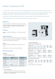
SICOP Datasheet 2010 Low Voltage Control Components Answers for industry.
Index Contents 2 Page No.
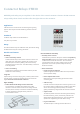
Contactor Relays 3TH30 Reliability and safety are pre-requisites in the choice of the control contactor. Siemens 3TH30 contactor relays satisfy these criteria and thus offer the right choice to the customer. Applications 3TH30 are used in control circuits for switching and signaling purpose. Also they are used for interfacing with the electronic circuits. Standards Contactor relay conforms to IS /IEC 60947-5-1. They also carry CE mark.
Selection and ordering data Contacts in basic unit MLFB - With AC coil MLFB - With DC coil 4NO 3TH30 40-0A.. 3TH30 40-0B.. 3NO+1NC 3TH30 31-0A.. 3TH30 31-0B.. 2NO+2NC 3TH30 22-0A.. 3TH30 22-0B.. Std. pkg. (nos.) 1 .. Please add coil voltage code AC Coil voltages Coil voltage 24 42 110 230 415 Code B0 D0 F0 P0 R0 DC Coil voltages Coil voltage 24 42 48 110 220 250 Code B4 D4 W4 F4 M4 N4 (Other coil voltages are also available.
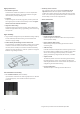
Accessories and ordering data 2. Add on blocks Auxiliary Contact Block 1. Surge suppressor It is used to reduce the effect of switching overvoltages created during the opening of inductive circuits. Typically they are mounted outside the body of the contactor relay, and are connected in parallel with the coil terminals. Various techniques for the suppression of switching overvoltages can be employed.
Power Contactors 3TF For more than 110 years, Siemens has been developing and manufacturing industrial control products. We offer a wide product range which fulfills the demands of our customers regarding performance and reliability. Our aim is to make industrial operation easier ensuring flexible mounting, modular construction and high functionality. With 3TF contactors Siemens has been offering a tried tested trusted solution to control, switch and protect your motors upto 250kW.
High performance • No duration upto 55°C Contactors are suitable for operation in service temperature upto 55°C without derating. This avoids selection of higher rated contactor, thereby reducing cost. • Long Life Superior design of current carrying parts, contact system and the magnet system increases the reliability results into higher electrical and mechanical endurance.
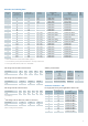
Selection and ordering data Contactor size Rated current (A) Ie AC3 at 415V, 50Hz, 3ph Motor kW at 415V 50Hz, 3ph 0 9 4 1NO $ 1NC $ 3TF30 10-0A.. 3TF30 01-0A.. 3TF30 10-0B.. 3TF30 01-0B.. 12 5.5 1NO $ 1NC $ 3TF31 10-0A.. 3TF31 01-0A.. 3TF31 10-0B.. 3TF31 01-0B.. 16 7.5 –$ 3TF32 00-0A.. 3TF32 00-0B.. 22 11 –$ 3TF33 00-0A.. 3TF33 00-0B.. 32 15 –$ 3TF34 00-0A.. 3TF34 00-0B.. 38 18.5 –$ 1 2 3 4 6 8 10 12 Auxiliary contacts AC 50 Hz coil Type Pl.
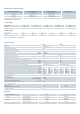
Technical data Contactor Size Permissible ambient temperature Storage Service 0 Type 3TF30 °C °C -55 to +80 -25 to +55 Maximum operating voltage V 690 Rated insulation voltage Ui (At Pollution Degree 3)1) V 690 Rated impulse strength Uimp kV 8 Cycles Cycles 15 x 106 15 x 106 Mechanical endurance (make/break operations) AC DC 1 3TF31 3TF32 2 3TF33 3TF34 3TF35 10 x 106 10 x 106 Rating of contactors for AC loads AC-1 duty, switching resistive load Rated operational current Ie Rating
3 3TF46 4 3TF47 3TF47 7 6 3TF48 3TF49 3TF50 8 3TF51 3TF52 10 3TF53 3TF54 12 3TF55 3TF56 3TF57 -55 to +80 -25 to +55 1000 1000 1000 1000 8 8 10 x 106 3 x 10⁶ 10 x 106 3 x 10⁶ 90 80 100 90 100 90 120 100 120 100 170 160 230 210 240 220 325 300 325 300 425 400 600 550 52 67 91 52 67 91 52 67 91 66 86 114 66 86 114 105 138 183 132 173 228 138 181 240 195 260 340 195 260 340 262 345 457 381 476 657 45 45 45 22 30 40 63 63 63 30 41.4 57.2 70 70 70 37 46 60.
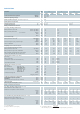
Power Contactors Technical Data Contactor Size Type Switching frequency z (Contactors without overload relay) No load AC DC at AC-1 at AC-2 at AC-3 at AC-4 Coil ratings (cold coil 1.0 x Us) Operation Cycles/hr Cycles/hr Cycles/hr Cycles/hr Cycles/hr Cycles/hr 0 3TF30 10,000 1,500 2,000 1,000 1,000 250 1 2 3TF31 3TF32 3TF33 10,000 1,500 2,000 1,000 1,000 250 5000 1,500 1,500 750 750 250 5000 1,500 1,500 750 750 250 3TF34 5000 1,500 1,200 750 750 250 Supply frequency Hz 50 50 Closing p.
4 6 8 10 12 3TF48 3TF49 3TF50 3TF51 3TF52 3TF53 3TF54 3TF55 3TF56 3TF57 5000 1,000 900 400 1000 300 5000 1,000 900 350 850 300 5000 1000 800 400 1000 300 5000 1000 800 300 750 200 5000 1000 800 300 700 200 5000 1000 750 250 500 130 3000 1000 800 300 700 200 3000 1000 750 250 500 130 3000 1000 700 200 500 150 2000 1000 500 170 420 150 50 50/60 Lower7) 50 50 330 0.5 32 0.23 550 0.45 39 0.24 420 2.7 500 2.7 50 50 910 0.38 58 0.26 1430 0.34 84 0.24 8766) 116) 2450 0.
Electrical Life Curves 3TF30 to 3TF49 contactors 3TF50 to 3TF57 contactors 14
Typical Circuit Diagrams Direct On Line starter a) Main circuit b) Control circuit for momentary-contact control S0 S1 S = = = K1 F1 F2 F3 = = = = ‘OFF’ Push button ‘ON’ Push button Maintained command switch Main contactor Main circuit fuse Overload relay Control circuit fuse c) Control circuit for maintained-contact control Forward / Reverse starter (Electrical Interlocking) Main circuit S0 S1 S2 S : : : : 'OFF' Push button 'ON Clockwise' Push button 'ON Anti-clockwise' Push button Selector Swi
Auto Transformer starter b) Auxiliary circuit for momentary-contact control S0 S1 K1 K2 K3 K5 = = = = = = K4 F1 F2 F3 = = = = a) Main Circuit Please refer page no. 70 for selection of switchgear for autotransformer starting method Internal connection diagram for DC coil circuits K1 : Sizes 3 to 6, 3TF46 to 3TF51 K1 : Sizes 8 to 12 3TF52 to 3TF56 K2 : 3TF30 10 OB.. for 3TF52-55 3TF32 00-OB.. for 3TF56 The control circuits indicated by dotted lines are to be wired by customer.
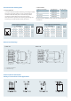
Terminal Designation Size 0, 3TF30/31 AC and DC Coil Size 3 to 12, 3TF46 to 3TF57 AC Coil Size 2, 3TF32/33/34/35 AC and DC Coil Size 3 to 12, 3TF46 to 3TF56 DC Coil Add-on contact block for 3TF30/31/32/33 Size 12, 3TF57 DC Coil Permissible Mounting Position 3TF30 to 3TF33 - AC operation 3TF30 to 3TF33 - DC operation 3TF34 to 3TF57 - AC operation 3TF46 to 3TF57 - DC operation 3TF34/35 - DC operation 17
Accessories and ordering data Surge suppressor (Varistor) for 3TF46-56 1. Mechanical interlocking kit Mechanical interlock is required when the supply from two different sources is available. Also the same is required for the application involving reversing of motor. Here two contactors are mechanically interlocked with the help of mechanical interlock kit. This ensures closing of only one contactor at a time. Thus prevents a short circuit upon load changeover from one contactor to another.
Spares and ordering data 1. Auxiliary Contact Blocks Add – on Contact Blocks: In-built contact configuration For Contactor 3TF30-35 Add on contact blocks Type Std. pkg. (nos.
Dimensional drawing 3TF30/31 AC Coil 3TF30/31 DC Coil Auxiliary contact block Identification tag 3TF32/33 AC Coil 3TF32/33 DC Coil 3TF34/35 AC Coil 3TF34/35 DC Coil Auxiliary contact block Identification tag 3TF30 to 3TF32, with mechanical interlock kit Notes 1) Dimensions for coil terminals Type a (AC coil) a (DC coil) b1 b2 c 3TF30/31 116 148 90 100 78 3TF32/33 127 159 91 101 85 2) Dimensions for mounting terminals Minimum clearance from insulated components = 5mm Mini
3TF46 and 3TF47 3TF47 7 3TF48 and 3TF49 3TF50 and 3TF51 Type a1 c Type a1 a2 b c φd 3TF48 8 107 3TF50 15 37 149 134 6.6(M6) 3TF49 10.5 116 3TF51 20 42 159 139 9(M8) 3TF54/55 3TF52 and 3TF53 Type a1 a2 b c φd 3TF52 20 42 174 154 6.6(M6) 3TF53 25 48 184 159 9(M8) Notes 4) Dimension for mounting. 1) Minimum clearance from insulated components = 3mm Minimum clearance from earthed components = 10mm 5) Dimension for power terminal.
3TF56/57 Type 3TF46/47/477/48/49 with Mechanical Interlock Kit a1 a2 b1 b c 3TF56 25 200 178 48 3TF57 30 209.
Useful information Categories of duty - as per IEC 947 / IS 13947 Current Utilisation Categories Typical Application AC AC1 AC2 AC3 AC4 AC5a AC5b AC6a AC6b AC7a AC7b AC8a AC8b Non-inductive or slightly inductive loads, resistance furnances Slipring motors; starting, switching off Squirrel-cage motors; starting, switching off motors during running(1) Squirrel-cage motors; starting, plugging, inching Switching of electric discharge lamp controls Switching of incandescent lamps Switching of transformers S
Recommended substitutes for discontinued 3TA/3UA19 For standard application (AC3 duty) AC3 rating 415V, 50Hz Discontinued contactor Size Discontinued bi-relay 3TA67 3TA76 7.8A 1 3TA21 3UA1911 16A 22A 3TA11 30A 3TA22 32A 2 3UA1928 3TF32 3TF33 3TF34 2 63A 70A 3TF46-Z 3TA24 4 105A 3 3TA16 3UA1938 110A 140A 170A 8 200A 3TA28 3UA66 250A 300A 12 3TB56 3UA66 – – – 400A 475A 3TF47-Z 4 6 3TA28-Y 3.8 3UA5000 3UA5200 10 12 7.5 11 15 3UA5500 # 18.
Contactors for Hoisting Duty AC slipring motors are most commonly used for the hoisting applications. AC2 duty pertains to starting and switching off the slipring motors. In case of hoisting duty breaking current is the starting current and frequency of switching is high. The table shows the making and breaking capacity at normal and at hoisting application where Ie indicates the rated full load current. Making Breaking During Normal operation at full load 2.
Technical Information A. Recommended selection of contactors for hoisting duty In hoisting operation, slipring motors are generally used. For this typical hoisting duty, we recommend the contactors listed in the following table. Contactor Type Stator Protection Maximum load current with hoisting motor. For intermittent duty S3 Rotor Protection Maximum load current with hoisting motor(Delta circuit).
Example 1 Motor rated current 150A. Selected contactor: 3TF5600 Contact endurance in operating cycles at 400V With inching of 0% 10% 20% 50% 100% 5.4 x 10⁶ 4.6 x 10⁶ 3.9 x 10⁶ 2.3 x 10⁶ 1.4 x 10⁶ Example 2 Maximum permitted motor rated current for a contact endurance of 2,000,000 operating cycles at 400V. Fig. 2 Contact endurance for mixed operation as a function of motor rated current. Motor on rated load, inching at 2.5 times motor rated current (slipring motor).
Draw a line from the point on the left-hand scale indicating the required number of operating cycles to the point on the right hand scale indicating the required number of operating cycles per hour. Then, from the point where this line intersects with the centre axis, draw a horizontal line to the left or right scale for the actual number of daily operating hours.
AC1 Duty Contactors 3TK5 When contactors are not required to make or break current but only carry the current, the contactors can be used to its full AC1 rating. Siemens 3TK5 AC1 duty contactors can be offered in such cases. Application 3TK5 AC1 duty contactors are widely used in sugar mills, DC drives and changeover applications. Also they can be offered for the applications like switching resistive loads, battery charging etc where the AC1 rating of the contactor is suitable.
Technical data Contactor Type 3TK50 Mechanical Endurance (make/break operations) Oprns 10 million Electrical Endurance in acc. with ACI duty at Ie (make/break operations) Oprns 0.5 million Rated insulation voltage Ui Permissible ambient temperature storage service Rated impulse withstand voltage Uimp V 1000 °C °C -55 to +80 -25 to +55 KV 8 3TK52 3TK54 3TK56 Rating of contactors for AC loads AC-1 duty, switching resistive load Raed operational current le Rating of three-phase loads p.
Accessories and ordering data: Spares and ordering data Auxiliary contact blocks: Contact kits: For Contactor 3TK5 Description Type Second 1NO+1NC Left 3TY7 561-1K Second 1NO+1NC Right 3TY7 561-1L Std. pkg. (nos.) Spare contact kit for Type 3TK50 02-0A.. 3TY7 500-0KA 1 3TK52 02-0A.. 3TY7 520-0KA 3TK54 02-0A.. 3TY7 540-0KA 3TK56 02-0A.. 3TY7 560-0KA Coils: For Contactor Type * 3TK50 3TY7 503-0A.. 3TK52 3TY7 523-0A.. 3TK54 3TY7 543-0A.. 3TK56 3TY7 563-0A.. Std. pkg. (nos.
Bimetal Overload Relays 3UA and 3UC The 3UA / 3UC thermal overload relays are suitable for customers from all industries, who want guaranteed optimum inverse time delayed protection of their electrical loads. The relays meet the requirements of IS/IEC 60947-4-1. Application 1 3UA overload relay: 3UA5/6 are 3 pole adjustable bi-metal overload relays mainly suitable for normal starting applications. They provide accurate and reliable protection to motors against overload as per CLASS 10A.
Recovery time After tripping due to overload, the thermal overload relays require some time until the bimetal strips have cooled down. The device can only be reset after the bimetal strips have cooled down. This time (recovery time) depends on the tripping characteristics and strength of the tripping current. The recovery time allows the load to cool down after tripping due to overload. Benefits and features High performance • In-built single phasing protection for -25 to 55° C.
Selection and ordering data: Setting range Type reference (A) Backup HRC fuse 3NA A (max) Mounting Std. pkg. (nos.) Setting range Type reference (A) Normal Motor Starting time Backup HRC fuse 3NA A (max) Mounting Std. pkg. (nos.) 3UA58 30 3UA50 0.1 0.16 0.25 - 0.16 0.25 0.4 3UA50 00-0A 3UA50 00-0C 3UA50 00-0E 2 2 2 0.4 0.63 0.8 - 0.63 1 1.25 3UA50 00-0G 3UA50 00-0J 3UA50 00-0K 2 2 4 1 1.25 1.6 2 - 1.60 2 2.5 3.2 3UA50 00-1A 3UA50 00-1B 3UA50 00-1C 3UA50 00-1D 6 6 6 10 2.5 3.
Technical Data Type 3UA50 3UA52 3UA55 3UA58 Trip class 3UA5830 3UA6230 3UA6830 3UC5030 3UC5830 10A 3UC6230 3UC6630 30 Phase failure protection 9 9 9 9 9 9 9 9 9 9 9 Changeover to auto-reset at site 9 9 9 9 9 9 9 9 9 9 9 RESET button (trip-free) Blue 9 9 9 9 9 9 9 9 9 9 9 Ambient temperature compensation 9 9 9 9 9 9 9 9 9 9 9 Trip indicator Green 9 9 9 9 9 9 9 9 9 9 9 TEST button Red 9 9 9 9 9 9 9 9 9 9 9 Terminal for cont
Characteristic Curves Tripping characteristics The current/time curves show the relationship between the tripping time from cold state and multiples of the set current Ie. When the relay is at operating temperature and carrying 100 % Ie, the tripping times are reduced to approximately 25 %. Tripping curve is applicable to 3-pole loads and 2-pole loads. For singlepole loads, the tripping curves lie between curves of 3-pole loads and 2-pole loads.
Accessories and ordering data 1. Adaptor: To convert contactor mounting relay to independent mounting, (Fig. 1) suitable for screw type mounting and 35 mm DIN rail mounting. 2. Protective cover*: To avoid tampering of the setting, auto manual mode or test button. (Fig. 2) 3. Reset cord*: To reset the relay in switchboard with door closed. (Length: 600 mm) (Fig. 3) 4. Reset plunger with funnel*: Instead of reset cord for resetting the relay in switchboard with door closed. (Fig. 4) Fig.
Dimensional Drawing 3UA50 with independent Mounting Adapter Type 3UX1 418 ** Dimension for the square OFF-button (stroke 3mm) Dimension for the round RESET-button (stroke 2.5mm) less 2.
3UA52/55 with independent mounting Type ** Dimension – For square OFF button (Stroke 3mm) – For Round RESET button (Stroke 2.5mm) less 2.5 mm 1) Suitable for DIN RAIL 35mm as per DIN EN 50022 3UA52 mounted on 3TF 32/33 * Minimum clearance from the earthed components ** Dimension – For square OFF button (Stroke 3mm) – For Round RESET button (Stroke 2.5mm) less 2.5mm 40 Dim a b 3UA52 + 3UX1420 M4 14.3 3UA55 + 3UX1425 M5 18.
3UA55 mounted on 3TF 34/35 * Minimum clearance from the earthed components ** Dimension – For square OFF button (Stroke 3mm) 1) Suitable for DIN RAIL 35mm as per DIN 50022 – For round RESET button (Stroke 2.5mm) less 2.5mm 3UA58 with independent mounting adaptor type 3UX1 421 3UA5800 mounted on 3TF46/47 3UA5800_.. Z1 mounted on 3TF48/49 * Dimension – For square OFF button (Stroke 3mm) – For round RESET button (Stroke = 2.5mm) less 2.
3UA5800_.. Z2 mounted on 3TF47 7 * Dimension – For square OFF button (Stroke 3mm) – For round RESET button (Stroke = 2.5mm) less 2.5mm 1) Minimum clearance from insulated components : 3mm Minimum clearance from earthed components: 10mm 3UA5830 with individual mounting adaptor type 3UX1 421 - OXA * Dimension – For square OFF button (Stroke 3mm) – For round RESET button (Stroke 2.5mm) less 2.
3UA6230 CT Operated Birelay ** Dimension – For square OFF button (Stroke 3mm) – For round RESET button (Stroke 2.5mm) less 2.5mm 3UA68 CT Operated Birelay ** Dimension – For TEST button (Stroke 3mm) – For Round RESET button (Stroke 2.5mm) less 2.
3UC50 CT Operated Birelay ** Dimension – For Square OFF button (Stroke 3mm) – For Round RESET button (Stroke 2.5mm) less 2.5mm 2) Suitable for DIN RAIL 75mm as per DIN EN 50023 3UC5830/3UC6230/3UC6630 CT Operated Birelay 44 Relay Type A B C D E F 3UC58 30 46 135 69 6.6 150 15x3 3UC62 30 46 140 69 9 160 20x3 3UC66 30-5B (200A) 50 146 69 9 160 20x3 3UC66 30-5C-5E(400A) 50 146 70 11 171 25x4 ** Dimension – For TEST button (Stroke 3mm) – For Round RESET button (Stroke 2.
Motor Protection Circuit Breakers 3VU13 and 3VU16 3VU13/3VU16 is suitable for use in fuseless motor feeders upto 11KW/22KW (25A/63A) respectively. 3VU motor protection circuit breakers are used for protection of motor against overload, single phasing and short-circuit faults. Applications • Motor Protection Circuit breakers type 3VU13 & 3VU16 offer overload, short circuit and phase loss protection for 3 phase motors upto 11kW and 22 kW respectively.
Current Limiting is achieved in 3VU as follows In case of a short circuit, the contacts are opened electrodynamically by the short circuit current. The instantaneous overcurrent release, through the switching mechanism, trips all the three poles of the breaker. A large arc voltage is quickly built up in the arc chamber limiting the short circuit current. Thus ensures faster fault clearing.
Technical Data According to DIN VDE 0660; IS/IEC 60947-1; IS/IEC 60947-2; IS/IEC 60947-4-1 Type 3VU13 3VU16 Number of poles 3 3 Max. rated current In • motor protection A 25 52 • distribution A 25 63 Permissible ambient temperature • at full rated current °C -20 ... +55 • in storage °C -50 ...
Technical data for accessories: 3VU13 3VU16 Undervoltage Release Consumption During Pick-up VA/W 10/6 Consumption During Running VA/W 4.7/2 Dropout V 0.7 to 0.35 X Ue Pickup V 85 to 110% of Ue Max Operating Time ms 20 Consumption VA/W 10/6 Max Continuous Rating Sec 5 Pickup V 0.7 to 1.1 X Ue Shunt Release Current Limiter for 3VU13 Rated current In 56 Amps Rated Voltage Ue 500 V, 50 / 60 Hz. Power Connection mm 2 2 x (1 to 6) Mounting on DIN Rail in any position.
Characteristic Curves Times set current Short circuit current Ik (effective) Time current characteristics of 3VU13 Cut off characteristics of 3VU1300-0MK00 Times set current Short circuit current Ik (effective) Time current characteristics of 3VU16 Cut off characteristics of 3VU1600-0MN00 49
Accessories: RHS Alarm contact (1NO + 1NC) When short circuit (and not overload) occurs, alarm contact 1NO+1NC changes over which can be used to give indication. We need to reset it manually after clearing of short circuit. It performs a function of reclosing lockout. and/or LHS Auxiliary Contact (1NO + 1NC) This contact can be added to the MPCB with or without built -in 1NO+1NC contact. Shunt Release Shunt trip is used for remotely tripping the MPCB.
Current-Limiter Connection diagrams a) b) c) d) e) f) Shunt release Under voltage release Integral auxiliary contacts Additional auxiliary contact for separate mounting Short circuit signaling contact Auxiliary contact of current limiter Diagram for 3VU13/16 and current limiter (applies for 3VU13 only) The breaking capacity of 3VU13 is 100kA upto 6A. However for 3VU circuit breakers with rated current of 8A and 10A the shortcircuit breaking capacity is 10kA.
Accessories and ordering data 3VU9131-3AA0 Add on Auxiliary block 1NO + NC 3VU9131-7AA00 S/C Trip indicating contacts 1NO + 1NC • 3VU9132-0AB55, 220/230V 50Hz • 3VU9132-0AB50, 24V/50Hz • 3VU9132-0AB73, DC 110-240V Shunt release 3VU9168-0KA00 Padlocking for Toggle Handle 3VU13/16 3VU9132-0AB15 220/230V 50Hz Under Voltage release 3 ∅ Insulated Bus-bar System for 3VU13 Also available 3RV19 25-5AB 3 ∅ feed-in Terminal, max rating 63A, for bus-bar system 3VU9135-1AB02 3 ∅ Busbars for 2 Breakers Max.
Dimensional Drawings 3VU13 circuit-breakers and accessories 3VU13 circuit-breakers can be combined with a) undervoltage or shunt release and/or b) short-circuit signalling switch and/or c) auxiliary contacts 3VU9 135–1AB02, 3VU9 135–1AB03, 3VU9 135–1AB04, 3VU9 135–1AB05 three-phase busbar 3VU9 138–2AB00 limiter The limiter has the same dimensions as the standard version of the 3VU13 circuit-breaker c d e f For 2 devices: 3VU9 135–1AB02 For 3 devices: 3VU9 135–1AB03 For 4 devices: 3VU9 135–1AB04 For 5 d
Door operating mechanism with extension shaft (300mm) with door interlock & padlocking facilities. Mounting bracket of 3VU 13/16 3VU9133-1PA01 for 3VU 13 3VU9163-1PA02 for 3VU 16 Handle (Figures in bracket are for 3VU 16) Mounting bracket Required space above arc chutes for 3VU13 and 3VU16 Minimum clearance to adjacent parts as well as non-insulated live parts.
Starters Overview Siemens caters with following types of starters to agricultural and industrial sector.
Application Benefits and features The main purpose of motor starters is to start the electrical motor by switching ON the contactor inside the starter. The relay inside the starter additionally protects the motor in case of overload and single phasing condition. The starter is nothing but a pre-wired assembly of contactor(s), relay and ON-OFF push buttons. Direct on line and star delta are two methods of starting the electric motors which is achieved by our DOL and star delta starter respectively.
Ordering data A1. DOL Starter in sheet steel housing, incl. birelay with single phasing protection Motor rating at 415V, 3ph, 50Hz 1) A4. Starter with hand reset facility, in sheet steel housing, incl. birelay with single phasing protection Type 1) Relay range A HP kW (DOL) 0.33 0.25 3TW42 90-1A.64 0.63-1 0.75 0.55 3TW42 90-1A.66 1-1.6 1 0.75 P 3TW42 90-1A.68 1.5 1.1 3TW42 90-1A.69 2-3.2 2 1.5 P 3TW42 90-1A.71 3.2-5 3 2.2 P 3TW42 90-1A.72 4-6.3 5 3.7 P 3TW42 90-1A.74 6.
B4. C. Industrial starter (starters w/o relay) Automatic star delta starter in open execution Motor rating at 415V, 3ph, 50Hz Type 2) Std. pkg. (nos.) Relay range HP kW (DOL) 12.5 9.3 3TE02000A.75 0.63-1 15 0.55 3TE02000A.77 1-1.6 20 0.75 3TE02000A.78 1.6-2.5 25 1.1 3TE02000A.79 2-3.2 Spares for starters 1 Spares for 3TW42 / 3LW42 CONTACTOR 3TW0 290-0A.51 Enter code for coil voltage, 50Hz (D for 230-400V, W for 415V) 2) C1.
Single line diagram SLD Spares for 3TE02 CONTACTOR 3TW0 311-0A*51 DOL - in S.S. Housing SLD– 3phase motor RAJA Direct-On-Line Starter 3TW42 90-1A CONTACTOR RELAY 3TW0 320-0A*51 3UW5002.. $ Main contact kit 3pole 3TX0 300-0YA0 Main contact kit 1pole 3TX0 300-0YA1 Coil 3TX0 303-0Y*6 Aux fixed contact 3TX0 300-1YB0 • Diagram shows connections made for contactor coils rated 200-400V (wide-band), 415V (320-455V), 50Hz, 440V (330-485V), 50Hz.
DOL - open execution SLD – 3phase motor DOL – open execution SLD – 1phase motor RAJA Direct-On-Line Starter (For Single Phase Motors) RAJA Direct-On-Line Starter (For Three Phase Motors) 3TW42 00-0A 3TW42 00-0A S01 - Remote OFF Push Button S11 - Remote ON Push Button S4 - Reset knob (Blue) Q1 - Contactor K1 - Bimetal Relay with SPP Feature R - Remote Reset Push Button • Connect 3/L2 to 2/T1 by cable of suitable size.
Star delta Starter Q1 = Line Contactor (2NO) Q2 = Star Contactor (1NO + 1NC) Q3 = Delta Contactor (1NO + 1NC) S0 = OFF Push Button S1 = ON Push Button S4 = Reset Push Button Q4 = Star Delta Timer with 1NO instantaneous and 1NO delayed Aux.
A2: DOL starter in open execution (contactor and relay are mounted on a plate) * Mounting dimensions 64 x 108 (Use M4 screws) B1: Handle operated Star delta starter M4 Earthing Screws at top end bottom * 62 Mounting dimensions 219 x 219 Use M4 screws for mounting
B2: Semi automatic star delta starter and B3: Fully automatic star delta starter B4.
C1: DOL without relay 3TW04 95-2A.. 3TW04 96-2A.. 3TW04 97-2A.. 3TW04 98-2A.. 3TW05 90-2A.. 3TW05 91-2A.. C2. 3TE04 94-2A.. 3TE04 95-2A.. 64 3TE04 96-2A.. 3TE04 97-2A..
Useful technical information Method of starting A. DOL starting method: Bimetal Overload Relay: The RAJA direct-on-line starter is fitted with 3UW50 relay. These relays are computer calibrated and therefore, offer accurate protection. The main benefit of this bimetal relay is the built-in single phasing protection in addition to the overload protection. This relay is automatic reset type and can not be reset by hand. Push buttons Push buttons are used for switching ‘ON’ and ‘OFF’ the starter.
In this starter, the changeover from ‘star’ to ‘delta’ is done manually through a control switch. A4. DOL starter with lockable off: Construction: It consists of a star-delta switch (3LAO), contactor (3TW02), an overload relay (3UW50), “Reset” push button and a safety ‘ON’ push button. Operation: This starter is exactly same as RAJA DOL starter with sheet steel housing but the relay needs to be reset manually by pressing OFF PB.
B3. Fully automatic Star-Delta Starter (3TE02) In this starter, the changeover from ‘star’ to ‘delta’ is done automatically after a preset time by using a timer. C. Industrial Starter: C1. DOL (3TW04): This starter is similar to RAJA DOL starter with sheet steel housing (3TW42901A). In order to offer flexibility of selecting exact 3UA relay range by the customer, this starter has only provision for mounting the bi-relay but the birelay is not provided in the starter.
Fuse protected selection type 2, lq = 50kA, IS/IEC: 60947-4-1 • The selection is valid only for complete Siemens combinations i.e. SDF + DIN Fuse + Contactor + Birelay (+ timer). • In case this combination is changed to accommodate another brand/rating of SDF/DIN Fuse/Contactor/BMR, it shall be the responsibility of the person making such a change to assure type 2 performance. • Selection is for normal starting conditions with starting time ≤ 6 seconds. For heavy starting applications (e.g.
Fuseless selection type 2, Iq = 50kA, IS/IEC: 60947-4-1 • The selection is valid only for complete Siemens combinations i.e. MPCB / MCCB + contactor + bi-relay (+timer). • In case this combination is changed to accommodate another brand/rating of MPCB/MCCB/contactor/BMR, it shall be the responsibility of the person making such a change to assure Type 2 performance. • Selection is for normal starting conditions with starting time ≤ 6 seconds. For heavy starting applications (e.g.
Recommended Selection of Switchgear for Autotransformer Starter - Fuseless SL Motor, 415V, 3Ph, 50Hz kW / HP Line contactor K3 MPCB / MCCB* IL Range MLFB Amp Amp Type A Transformer contactor K2 for Tranformer tapping % star contactor K1 = same as transformer contactor K2 80% 70% 65% Overload Relay 50% Type A Type A Type A Type A Type A 2.2 / 3 4.8 3RV10211FC10 5 3TF30 9 3TF30 9 3TF30 9 3TF30 9 3TF30 9 – – 3.7 / 5 7.
Notes ○ ○ ○ ○ ○ ○ ○ ○ ○ ○ ○ ○ ○ ○ ○ ○ ○ ○ ○ ○ ○ ○ ○ ○ ○ ○ ○ ○ ○ ○ ○ ○ ○ ○ ○ ○ ○ ○ ○ ○ ○ ○ ○ ○ ○ ○ ○ ○ ○ ○ ○ ○ ○ ○ ○ ○ ○ ○ ○ ○ ○ ○ ○ ○ ○ ○ ○ ○ ○ ○ ○ ○ ○ ○ ○ ○ ○ ○ ○ ○ ○ ○ ○ ○ ○ ○ ○ ○ ○ ○ ○ ○ ○ ○ ○ ○ ○ ○ ○ ○ ○ ○ ○ ○ ○ ○ ○ ○ ○ ○ ○ ○ ○ ○ ○ ○ ○ ○ ○ ○ ○ ○ ○ ○ ○ ○ ○ ○ ○ ○ ○ ○ ○ ○ ○ ○ ○ ○ ○ ○ ○ ○ ○ ○ ○ ○ ○ ○ ○ ○ ○ ○ ○ ○ ○ ○ ○ ○ ○ ○ ○ ○ ○ ○ ○ ○ ○ ○ ○
Your partners Sales offices: Ahmedabad Chennai Kolkata Nagpur 3rd Floor, Prerna Arbour Girish Cold Drinks Cross Roads, Off. C. G.