SAPHIR ACX 32 Hardware Description Basic Documentation Revision 2.0 Controller Range ACX 32 CE2P3689en 25.11.
Siemens Building Technologies HVAC Products Gubelstrasse 22 CH 6301 Zug Tel. 41 41-724 2424 Fax 41 41-724 3522 www.sbt.siemens.com © 2004 Siemens Switzerland Ltd Subject to alterations 2/42 Siemens Building Technologies HVAC Products Hardware Description Foreword and Notes on Use CE2P3689en 25.11.
Contents 1 Foreword and Notes on Use ......................................................................... 5 1.1 Foreword....................................................................................................... 5 1.2 Notes on Use ................................................................................................ 5 1.3 Abbreviations ................................................................................................ 6 1.4 Chapters in this Document .........
5.2.1 Behavior in the Event of Malfunction...........................................................30 5.2.2 Connectors ..................................................................................................31 5.3 Wiring Examples .........................................................................................33 5.3.1 Basic Wiring of SAPHIR ..............................................................................33 5.3.2 SAPHIR with Digital Outputs .........................
1 Foreword and Notes on Use 1.1 Foreword Rising demands on building systems engineering and building management are reflected in increasing automation of building services. In the area of controls for the HVAC OEM business, the rising demands are being met with the new "SAPHIR" system, which will supersede the existing Siemens system "COMPAS" in the lower price/performance range. The SAPHIR OEM primary controller is a powerful DDC compact controller that has been developed for use in HVAC applications.
1.3 Abbreviations HVAC ADC NMI PWM SPI MSR ID HMI DDC Heating, Ventilation, Air-Conditioning Analog-to-Digital Converter Non-Maskable Interrupt Pulse Width Modulation Serial Peripheral Interface Mess-Steuer-Regeltechnik (instrumentation and control) Identification Human-Machine Interface Direct Digital Control Passages introduced by this symbol indicate a warning to help prevent incorrect operation. STOP Passages introduced by this symbol indicate that the text must be read with special attention.
2 System Description The following contains an overall description of a SAPHIR system. 2.1 General The SAPHIR system comprises a basic device, operating system software for the basic device, and engineering software, as well as additional tools, such as SACUS or WEBCC, which provide for implementation of HVAC applications. Two module slots, to which communication modules can be attached, provide extension possibilities.
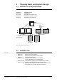
3 Planning Basis and System Design 3.1 SAPHIR ACX 32 System Design The following provides a current list of the SAPHIR components: ACX3x.xxx ACX8x.xxx ACX5x.xxx ACX4x.xxx ACX9x.xxx SAPHIR controller SAPHIR HMI SAPHIR communication cards SAPHIR I/O expansion modules SAPHIR plug-in terminal set ACX5x… ACX5x.. communication cards Kommunikationskarten ACX4x ACX4x I/Oexpansion ErweiterungsI/O Module modules ACX90.14 ACX90.14 plug-in terminals Steckklemmen ACX32… ACX32….
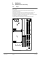
4 Hardware 4.1 SAPHIR Control Assembly 4.1.1 Design The SAPHIR control assembly comprises a motherboard and two different optional plug-in modules. The motherboard is a 6-layer printed circuit board that contains all electronic components and connectors. Communication connection solutions can be implemented on the modules. The motherboard has two 55-pin socket connectors for connecting the modules. Module 1 Module 2 The motherboard is installed in a double sheet metal housing.
4.1.
4.2 General data Interfaces: Technical data Dimensions: Overall device Motherboard Modules Weight Color Attachment Supply voltage Current consumption: Peripheral interfaces (X1…X12) Serial interface (X13) External interface (X14) Module interface (X15) Module interface (X16) 280 mm x 158 mm x 54 mm 280 mm x 150 mm, 6x multilayer 105 mm x 76 mm Approx. 1.3 kg RAL 7016 (dark green) Mounting on 35 x 7.5 mm DIN top-hat rail 24 VAC (±15%) or 26…35 VDC Approx. 0.
PTC, NTC thermistors: − Sensor current − Temperature measurement Digital input − Input frequency Fast binary inputs BI1…BI4: Digital input − Input frequency Analog outputs AO1…AO4 (X9): Analog outputs AO5…AO8 (X10): 400 µA Up to approx. 4.5 kΩ resistance value (from 4.5 kΩ with parallel resistance) External supply not possible. Voltage supplied by device; 24 V at max. 4.5 mA, non-floating, i.e. use floating contacts only! Max. 2 Hz External supply not possible.
Product safety 4.3 4.3.1 Automatic electrical controls for household and similar use EN 60 730-1 or IEC 60 730-1 Interfaces RS232 Interface For general service and diagnostic purposes, the RS232 interface is brought out to connector X13. In addition to software loading functions, such as the bootstrap loader, operating system loading and MSR tasks, the RS232 interface is also used to connect an external monitoring and operator unit.
4.3.2 External Communication Interface In case the number of data points in the ACX32 controller is insufficient for a given application, an additional, external communication interface provides for connection of external slave I/O modules. The interface is physically configured as an RS422 bus interface on D-SUB jack X14. The signal lines are terminated internally with 120 Ω. The overall system comprises an ACX32 master and up to 15 slave I/O modules (see section 5.3.10 for an example).
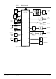
4.3.3 Module Interface In order to implement communication application solutions, SAPHIR has two equivalent module slots, which makes it very versatile with regard to connectivity, and enables it to operate with a number of different communication busses. The two module interfaces are connected directly to the microcontroller's data/address/control bus. The modules' hardware identifiers are read via an ID signal.
4.4 4.4.1 Inputs and Outputs Relay Outputs 8 DC-decoupled relay outputs BO1…BO8 provide for potential-free control of process operations (motors, actuators, lamps etc). The digital outputs are designed as floating relay contacts. The contacts support a load of 230 VAC and a maximum of 2 A. The relays are arranged in two groups: • BO1…BO4 changeover • BO5…BO8 changeover Use only 1 working voltage within each group: 230 VAC or safety extra-low voltage.
4.4.2 Fast Binary Inputs The four fast binary inputs BI1…BI4 are used to interrogate switching states, and for counting switching pulses at a maximum switching frequency of 50 Hz. These inputs are connected directly to interrupt-generating ports of the microcontroller. This provides for a quick reaction to signal changes. Only floating contacts must be connected to the binary inputs. The contacts are interrogated with approx. 24 V / 6 mA. The counter frequency is restricted to approx.
4.4.3 PWM analog outputs Analog Outputs The 4 PWM analog outputs AO1…AO4 are implemented via the controller's internal PWM outputs. The PWM signal is converted to the analog range of 0…10 VAC via an RC element and an amplifier module. A feedback circuit connecting the analog outputs to the controller's internal analog inputs is used to calibrate the outputs. The PWM analog outputs have the following features: • AO1...AO4 produce voltages between 0...
SAPHIR V X9.1 X9.3 AA1 AO1 V X9.2 X9.3 AO2 AA2 V X10.4 X10.6 AA7 AO7 X10.5 X10.6 AO8 AA8 I Connect broadly Schirmshield großflächig auf to theSc shield bus legen hirmschiene Figure 6: Analog output connection Cables The cross-section of the connecting wires should not exceed 1.5 mm² because of the Cage Clamp terminals. EMC measures Use shielded cables as signal cables. Each analog output should be connected to a twisted pair.
4.4.4 Universal Inputs The central element of the universal inputs is a sigma-delta ADC. One of the 14 universal inputs is connected to the ADC via a multiplexer and analog switch. A scan list defined via the software determines the processing sequence. The 14 universal inputs UI1...UI14 have a common reference point and are electrically connected to the SAPHIR unit.
24 VAC SAPHIR PT1000 + X11.1 0 ... 10 VDC Voltage input Spannungseingang - X11.2 M Active transducer, Aktiver Messumformer, 4-wire connection 4-Leiter-Anschluss 24 VAC PT1000 + X11.3 0 ... 10 VDC Voltage input Spannungseingang - X11.4 M Active transducer, Aktiver Messumformer, 3-wire connection 3-Leiter-Anschluss 24 VAC PT1000 + X11.5 0 ... 20mA Current input Stromeingang - X11.
Voltage input Electrical values Voltage inputs process 0...+10 VDC signals. Input voltage: U = 0…10 VDC Input impedance: approx. 100 kΩ Resolution: up to 12 bit (default 10 bit) Current input In the case of current inputs, a 100 Ω shunt must be connected externally in parallel to the universal input. Current measurement is performed indirectly via a voltage measurement across the shunt.
4.6 4.6.1 Indications and Switches Light-Emitting Diodes (LEDs) The SAPHIR unit is equipped with four LEDs for optical status indication. The LEDs are controlled via an external port that is addressed by the microcontroller's chip select signal (CS2). LED name CTRL (LED1) FAULT (LED2) COM (LED3) OK (LED4) Indication meanings: – Individual ACX32 Port Bit 0 Bit 2 Bit 4 Bit 7 The functionality of the LEDs is briefly described here. Application with an ACX32 with no communication card (RCC) installed.
Operating state Normal status Task stopped I/O error Controller error LED indication CTRL flashes green OK flashes green at high frequency FAULT is off COM indicates RCC message traffic CTRL is off OK flashes at high frequency FAULT is permanently red COM is off CTRL flashes OK flashes at high frequency FAULT is permanently red COM indicates RCC message traffic FAULT is permanently red! No other LED is on or flashing.
4.6.2 DIL Switches A 4x DIL switch is installed on the SAPHIR unit. The ON position of a switch supplies the "0" state at the corresponding port pin. The DIL switches are read via port P5 of the controller. DIL switch S6 Bit 0 Bit 1 Bit 2 Bit 3 4.6.3 Input P5.4 P5.5 P5.6 P5.7 Bridges The bootstrap loader is activated via bridge X19. The bridge must be inserted before the SAPHIR unit is powered up (see Fig. 2).
4.7 Supply Voltages The SAPHIR unit is supplied with 24 VAC (±15%) or 26…35 VDC via plug-in terminal strip X1 (terminals X1.1 and X1.2). L1 N 230 VAC 50/60 Hz SAPHIR 2 AT X1.1 24 VAC X1.
4.7.1 5V Logic Supply This is produced from the supply voltage after rectification and smoothing via a DC/DC converter. A reset generator monitors the voltage; it is triggered at a voltage of approx. 4.55 V at which it generates a reset. 4.7.2 30 VDC supply This is produced directly from the supply voltage after rectification and smoothing. Since the voltage is not controlled, it can vary in a range of approx. 26...35 V.
5 Assembly, Installation and Setup Guidelines 5.1 General Setup Notes With the use of electronic components in automation, increasing attention must be paid to electromagnetic immunity. Typical sources of interference noise such as relays, fluorescent lamps, converters, HF generators, commutator rotors and switching controllers generate high-frequency signals that are injected directly, inductively or capacitively into the module where they can disturb or even destroy it.
5.2 SAPHIR ACX32 Figure 9: SAPHIR ACX32... Accidental connection of voltages greater than AC 29 V (e.g. AC 240 V) to the low-voltage connections will destroy the device. STOP The connection sequence of the SAPHIR device is as follows: First connect the peripheral signals, then the power supply. In order to protect against accidental contact with relay connections at voltages of Ueff > 42 V, the device must be installed in an enclosure (preferably a control panel).
Position of der the DIN top-hat rail EN 50022, 37 x 7.5 mm Position Hutschiene 28.5 226 ACX94.04 Ground terminal Position der Erdungslasche 283 Figure 10: Snap-in mounting of unit ACX32... on a top-hat rail using ACX94.04 5.2.1 Behavior in the Event of Malfunction Check the following in case of malfunction: • 24 V power supply • Correct connection of plug-in cables • Correct connection of peripheral devices • Watchdog error occurred? • Diagnostics via LEDs on device front (see section 4.6.
5.2.2 Connectors WAGO Cage Clamp female connectors are provided for connection of the power supply and peripheral signals to the SAPHIR unit.
Ordering data: Cage Clamp equipment WAGO peripheral connectors Connector Contact spacing in mm Conductor cross section in mm² 5.08 7.62 3.81 3.81 3.81 0.08…2.5 0.08…2.5 0.08…1.5 0.08…1.5 0.08…1.5 X1 X3,X4,X5,X6 X7,X8 X9,X10 X11,X12 Order number without strain relief with strain relief 231-302/026-000 231-706/026-000 734-204 734-206 734-214 /032-000 /034-000 /033-000 /033-000 /035-000 Figure 12: Ordering data The service and diagnostics interface is adapted via an RJ45 connector.
5.3 Wiring Examples 5.3.1 Basic Wiring of SAPHIR The following illustration shows a wiring example of the SAPHIR unit. STOP The 24 VAC supply voltages for the SAPHIR unit and the active transmitters/sensors must be generated via a transformer with two separate windings (short circuit hazard). Alternatively, two 24 V transformers can be used.
5.3.2 SAPHIR with Digital Outputs Wiring example with relay outputs: AC24…250V, relay outputs Relaisausgänge2A 24...250VAC 6A X3 X4 X5 X6 1 2 3 4 5 6 1 2 3 4 5 6 1 2 3 4 5 6 1 2 3 4 5 6 Figure 14: Relay outputs Any suppressor circuit, interference suppression etc. must be provided externally according to the application! 5.3.3 SAPHIR with Fast Counter Inputs Wiring example with the digital inputs configured as fast counter inputs (max. 50 Hz).
5.3.4 SAPHIR with Analog Outputs Analog outputs Analogausgänge X9 X10 + + - + + - + + - + + - 1 2 3 4 5 6 1 2 3 4 5 6 SP SN G G0 Y AC V rotary actuator 2424 VACDrehantrieb 0…10 V input 0.DC ..10VDC-Eingang Figure 16: Analog outputs 35/42 Siemens Building Technologies HVAC Products Hardware Description Assembly, Installation and Setup Guidelines CE2P3689en 25.11.
5.3.5 SAPHIR with Passive Sensor Wiring example with Ni1000, Pt1000 or Pt100 configured as a passive sensor. Universal inputs Universaleingänge X11 + - + - + - + - + - + - + 1 2 3 4 5 6 7 8 9 10 11 12 13 14 Pt1000, Pt100, Ni1000 Temperatursensor temperature sensor Pt1000,Pt100,Ni1000 Figure 17: Passive sensor 36/42 Siemens Building Technologies HVAC Products Hardware Description Assembly, Installation and Setup Guidelines CE2P3689en 25.11.
5.3.6 SAPHIR with Temperature Sensor Wiring example with NTC or PTC temperature sensor. An NTC/PTC sensor is connected to universal input UI11 (X12.7, X12.8). Above a resistance value of approx. 4.5 kΩ, an external shunt resistor must be connected. Inquire first whether an NTC/PTC sensor characteristic has been implemented in the software. Universaleingänge Universal inputs X11 + - + - + - + - + - + - + - Shunt resistor erstand Parallelwid fromab approx. 4.5 kOhm ca.
5.3.7 SAPHIR with Active Sensor Wiring example with an active sensor with 0…20 mA or 4…20 mA output signal. An active sensor with a 0…20 mA current output is connected to universal input UI3 (X11.5, X11.6). For this purpose, a 100 Ω shunt resistor must be connected in parallel to the input. The accuracy of the current input is largely determined by the accuracy of the shunt resistor. A resistor with a tolerance of 0.1 % is recommended.
5.3.8 SAPHIR with Active Sensor Wiring example with an active sensor with DC 0…10 V output signal. Universal inputs Universaleingänge X12 + - + - + - + - + - + - + 1 2 3 4 5 6 7 8 9 10 11 12 13 14 SP SN B M G Active with Aktiversensor Sensor mit DC 0-100…10 VDCV- output Ausgang Figure 20: Active sensor with DC 10 V output signal 39/42 Siemens Building Technologies HVAC Products Hardware Description Assembly, Installation and Setup Guidelines CE2P3689en 25.11.
5.3.9 SAPHIR with Digital Input Wiring example with 2 digital inputs, e.g. status signal. Universaleingänge Universal inputs X12 + - + - + - + - + - + - + 1 2 3 4 5 6 7 8 9 10 11 12 13 14 inputsge DDigital igitaleingän Figure 21: Digital inputs 40/42 Siemens Building Technologies HVAC Products Hardware Description Assembly, Installation and Setup Guidelines CE2P3689en 25.11.
5.3.10 SAPHIR with Slave Modules Wiring example of ACX32 master and AXC42.12 or ACX41.
Siemens Building Technologies HVAC Products Gubelstrasse 22 CH-6301 Zug Tel. +41 41-724 24 24 Fax +41 41-724 35 22 www.sbt.siemens.com © 2004 Siemens Switzerland Ltd Subject to change 42/42 Siemens Building Technologies HVAC Products Hardware Description CE2P3689en 25.11.