
User Manual

23/29
Building Technologies CC1N7817en
28.03.2018
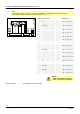
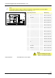
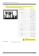
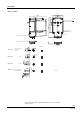
Connection diagrams and connection terminals (cont’d)
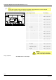
Electronic version with independent auxiliary switch
Β
Note!
For the sake of clarity, the plug-in contacts do not appear in sequential order in the circuit diagram.
Consecutive numbers are printed on the unit, however, e.g. 1…7.
x
x
x
x
X
2
V
9
M
VI
I
2 78
X
1
1
1
4
-
2
0
m
A
G
N
D
2
6
5
7
8
1
7
d
2
1
/
0
4
1
5
IV
453
2
Low-voltage terminals Dimensioning
X1-1 4...20 mA Input max. 20 mA
to X1-2
X1-2 GND Input ---
Mains voltage terminals Dimensioning
X2-1 Open position reached (I) Output AC 120 V / AC 230 V
max. 10 mA, cosι >0.9
X2-2 Open / high-fire (I) Input AC 120 V / AC 230 V
max. 1 A, cosι >0.9 *
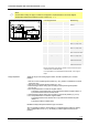
X2-3 Auxiliary switch AUX (IV)
NO contact
Output AC 120 V / AC 230 V
max. 1 A, cosι >0.9
X2-4 Auxiliary switch AUX (IV) Input AC 120 V / AC 230 V
max. 1 A, cosι >0.9
X2-5 Auxiliary switch AUX (IV) /
NC opener
Output AC 120 V / AC 230 V
max. 1 A, cosι >0.9
X2-6 Low-fire position / ignition
load position reached (V,
VI)
Output AC 120 V / AC 230 V
max. 10 mA, cosι >0.9
X2-7 Close / ignition (VI) Input AC 120 V / AC 230 V
max. 1 A, cosι >0.9 *
X2-8 Neutral Input AC 120 V / AC 230 V
max. 60 mA / 30 mA
X2-9 Controller release Input AC 120 V / AC 230 V
max. 60 mA / 30 mA
* Only the control lines to the burner controls or to the control unit may be
connected at the marked terminals.
It is not permitted to connect additional external loads, such as signal
lamps.
See SQM4x.x4xxxx in this chapter.
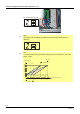
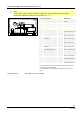
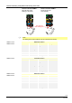
SQM4x.x5xxxx
Range adjustment