
User Manual


16/15
Building Technologies Division CC1N7636en
15.06.2016
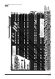
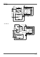
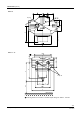
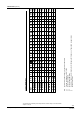
Dimensions (cont´d)
Table of dimensions
Type
VGG10.15...
VGG10.20...
VGG10.25...
VGG10.40...
VGG10.50...
VGG10.80...
VGF10.50...
VGF10.65...
VGF10.80...
DN
1)
1/2"
3/4"
1"
1 1/2"
2"
3"
DN50
DN65
DN80
A
---
---
---
---
---
---
13
16,5
19
B
---
---
---
---
---
---
3
3
3
C
96
96
96
126
130
D
79
79
79
102
107
163
107
163
163
E
80
80
80
126
126
185
126
185
185
F
109
109
109
150
170
310
230
290
310
G
---
---
---
---
---
110
---
108
118
G
´
---
---
---
---
---
110
---
108
118
H
---
---
---
---
---
68
---
95
102
J
32
32
32
41
50
100
50
92
100
K
---
---
---
---
---
---
19
19
19
L
---
---
---
---
---
---
165
185
200
M
---
---
---
---
---
---
125
145
160
N
---
---
---
---
---
---
102
120
131
P
---
---
---
---
---
---
45°
45°
22,5°
Q
---
---
---
---
---
---
90°
90°
45°
R
---
---
---
---
---
---
4
4
8
S
28
28
28
34
34
---
42
---
---
T
31
31
31
34
34
62
42
---
---
SW
*
46
46
46
60
75
120
---
---
---
kg
0,8
0,8
0,75
1,4
1,95
13,4
7,5
15,3
17,9
2)
3)
---
---
---
---
DN Nominal size, dimension for connection of medium
1) Flange conforming to ISO 7005-2
2) With stroke limitation
3) Without stroke limitation
R Number of boreholes; for standards for flanges and threads, see Type summary gas valves
* Width across flats
2016 Siemens AG Building Technologies Division, Berliner Ring 23, D-76437 Rastatt
Subject to change!