7 Control Units 761 LEC1... Control unit for double- or multiflame supervision of oil, gas or forced draft oil / gas burners of any fuel throughput, suited for continuous or intermittent operation. The LEC1... and this Data Sheet are intended for use by OEMs which integrate the control units in their products! Use The LEC1...
Use (cont´d) The following types of flame safeguards are available: LAE10 For the supervision of oil burners with an active photocell detector RAR… in intermittent operation LFE10 For the supervision with an ionization probe (gas burners) or with UV detectors QRA… (gas, oil or dual-fuel burners, with or without ignition spark proving) in intermittent operation LFE50 For the supervision with UV detectors QRA50… / QRA51…(gas, oil or dual-fuel burners) in intermittent or continuous operation All units c
Warning notes To avoid injury to persons, damage to property or the environment, the following warning notes should be observed! Only authorized staff may open, interfere with or modify the unit! · · · · · · · All activities (mounting, installation and service work, etc.
Commissioning notes · · · · · Continuous display of the program sequence in the viewing window: It is also possible to program the unit by means of a changeover link (UL3) in a way that the programming mechanism does not stop in case of lockout, but that it runs to the end of the program.
Standards and certificates Applied directives: · Low-voltage directive · Electromagnetic compatibility EMC (immunity) *) 2014/35/EU 2014/30/EU *) The compliance with EMC emission requirements must be checked after the burner control is installed in equipment C Note! These devices may only be used as replacements within the EU and EFTA countries.
Mechanical design The LEC1... as well as the flame safeguards LAE10 and LFE10 are of plug-in design and suitable for mounting in any position on the burner, on control desks or in control panels. The spacious terminal bases and housings are made of impact-proof and heat-resistant plastic. The programming mechanism of the unit (driven by a synchronous motor), its auxiliary relays and all other switching, control and adjusting elements are mounted on robust printed circuit boards. Type summary Article no.
Accessories (to be ordered separately) Article no. Type BPZ:AGG41041713 (EC) AGG41041713 (EC) Terminal base · To be ordered as a separate item · For M16 x 1.5 BPZ:AGG12.1 AGG12.
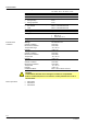
Technical data General unit data Mains voltage Mains frequency Unit fuse, built-in External fuse Power consumption · During startup · During operation Permissible load on the control outputs · Per terminal · Total Degree of protection Mounting position Cable glands Environmental conditions AC 220 V -15 %...AC 240 V +10 % AC 100 V -15 %...AC 110 V +10 % 50...60 Hz ±6 % T6.3H250V to DIN EN 60 127 Max. 10 A (slow) 8 VA 5 VA Weight Max. 4 A to VDE 0660 AC3 Max.
Function The following description of the unit’s function refers to the startup and supervision of a single burner. With multiflame supervision, all burners connected to the control unit are put into operation and supervised simultaneously in the same manner. A fault causing lockout of one of the burners therefore results in the shutdown of all burners.
Function (cont´d) Burner startup with ignition spark proving In principle, the program sequence is the same as with burner startup without ignition spark proving. Exceptions: · If the UV flame detector does not receive any input signal during the short preignition time (UL2 on «Short preignition»), lockout occurs before any gas is released, i.e. safety time TSA = 0 seconds · With ignition spark proving, the safety time for the pilot burner can only be adjusted between 0...
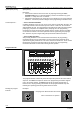
Adjustment facilities on the unit Before making any adjustments, disconnect the unit from the mains supply Loosen all 6 retaining screws and only remove the unit cover The numbering of the switching cams always starts from the motor The camshaft can be manually turned into any position (clockwise direction of rotation as seen from the motor) 7761p03/0201 · · · · UL1 N1 N2 N3 N4 N5 N7 N8 Setting elements: N1 Cam 1, fixed N2 Cam 2, adjustable (1st safety time) N3 Cam 3 adjustable (1st safety time) N4 Cam
Adjustment facilities on the unit (cont´d) Adjusting the safety times «TSA» The safety times are adjusted by setting the red cams of the programming mechanism. Their time marks serve as a setting aid. After the adjustment, the fixing screws of the cams must be tightened very carefully to make any unintentional readjustment impossible.
Basic diagram P(R) H SB EK2* 1 16 AS EK1* UL3 br1 VIII ar3 ar1 VIII b a a b XI I I IX IX b hr11 a 8 18 P (R) 7 P W 3 FW 6 GP 7 T T R 3 3 5 19 ~ 4 6 9 N M1 NTC y z LK N M 4 13 14 21 (11) P LP 22 5 ~ 4 15 20 hr21 II a X b HR2 XI hr12 IV VI I a XI I I b IV a b UL2 AR III VI a V b ar2 br2 L1 BR UL1 HR1 SM 2 6 5 10 7 11 17 12 L2 Z 7761a01/1102 N (Mp) BV1 (BV1) BV2 M2 BV3 M ~ * Do not press EK… for more than 10 seconds! P(R) L
Sequence diagram of programming mechanism Maximum permissible afterburn time is 7 seconds - from the beginning of postpurge time «t6». I 81 a b II TSA79 III TSA´ a b IV 67 t4 t9 90 V t3 ´ t5 a b VI 93 t3 VII 70 a b VIII 3 a b IX t7 X t1 0 10 XI 66 a b XII t1 a b XIII t11 63 t12 7761d01/0201 t8 t6 T Legend AS AR BR BV... (BV...) L1 L2 L3 Unit fuse Load relay with contacts «ar...» Lockout relay with contacts «br...
Connection examples and sequence diagrams For connection examples and switching program for flame supervision with DETACTOGYRâ LFE50..., refer to Data Sheet 7783. Startup with long preignition «t3» and checked actuator control. Air pressure supervision from the start to controlled shutdown. No load control. Required type of flame safeguards: LAE10... with selenium photocell detector RAR...
Connection examples and sequence diagrams (cont’d) Startup with short preignition (3 seconds) and checked actuator control. Required type of flame safeguards: LFE10... with UV detectors QRA... or ionization probe. Double- or multiflame supervision of gas burners (expanding flame burners) LEC1... 1 16 2 13 14 15 12 19 18 8 9 4 UL.
Connection examples and sequence diagrams (cont’d) Double- or multiflame supervision of burners for selectable operation with oil or gas (expanding flame burner) Startup with short preignition (3 seconds) and checked actuator control. Control of the 2nd output stage via on / off controller «R2». Required type of flame safeguards: LFE10... with UV detectors QRA... M1 M c1 e1 2 12 LEC1... (17) 13 14 153 FW 3 4 SB 6 H M2 M c2 e2 L2 7 3 5 4 7 6 5 FW 18 8 19 4 9 T c1/c2 UL.
Connection examples and sequence diagrams (cont’d) Double- or multiflame supervision of modulating burners Including checked actuator control. Required type of flame safeguards: For oil LAE10 with active selenium photocell detectors RAR... For gas LFE10 with UV detectors QRA... or ionization probe For oil / gas LFE10 with UV detectors QRA... 16 1 2 13 14 12 19 18 8 9 20 22 21 10 11 e1 EK2 17 6 7 e2 c1 d1 c1 d1 FW * c1 e1 L ** c2 e2 Q a 11 L2 SQ...
Dimensions 2 2 Dimensions in mm LEC1... 116 116 LEC1... M16 x 1,5 Pg11/3/4"-16DNF 1 17 1 210 B A 17 AGG12.1 AGG41041713 (EC) A 25 140 25 13,5 14,5 SG EK A B 7761m01/1102 A 17,2 4,5 C 139,4 17,2 C 4,5 36,7 46,7 18,9 33 105 69,7 C 33 17,7 33 33 33 174 209,4 9 17,7 To remove the control unit from the plug-in base, loosen only the 4 screws A. To remove the unit cover, also loosen the 2 screws B.