7 Oil Burner Controls 161 LAE1... Oil burner controls for use with burners of any capacity in intermittent operation. For safety reasons, at least one controlled shutdown must take place every 24 hours. The LAE1... and this Data Sheet are intended for use by OEMs which integrate the burner controls in their products.
Use (cont´d) Specific features ∂ ∂ ∂ ∂ ∂ ∂ ∂ ∂ ∂ ∂ ∂ ∂ Prepurge time adjustable between 8 and 63 seconds Operation with or without postpurge (optional) Fully automatic control of air damper, if required (with any actuator running time) Possibility of air check, in connection with a functional check of the air pressure switch prior to startup Ignition optional (directly ignition or with pilot burner) Preignition time adjustable («long» - during prepurge, «short» - 3 seconds) Safety time adjustable between
Electrical connection of flame detectors It is important to achieve practically disturbance- and loss-free signal transmission: ∂ Never run the detector cable together with other cables – Line capacitance reduces the magnitude of the flame signal – Use a separate cable ∂ Observe the maximum permissible detector cable lengths (refer to «Technical data») Commissioning notes When commissioning the plant or when doing maintenance work, make the following safety checks: Safety check to be carried out Anticipate
Life cycle Burner controls has a designed lifetime* of 250,000 burner startup cycles which, under normal operating conditions in heating mode, correspond to approx. 10 years of usage (starting from the production date given on the type field). This is based on the endurance tests specified in the standard EN 230. A summary of the conditions has been published by the European Control Manufacturers Association (Afecor) (www.afecor.org).
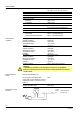
Type summary Factory settings Article no. Type * Mains voltage Hz t1 TSA t9 BPZ:LAE1/1355 LAE1/1355 AC 220...240 V 50 30 s 5s 5s BPZ:LAE1/8846 LAE1/8846 AC 220...240 V 50 30 s 2s 2s BPZ:LAE1/8864 LAE1/8864 AC 100...110 V 60 30 s 2s 2s BPZ:LAE1/8865 LAE1/8865 AC 220...
Technical data General unit data Mains voltage AC 220 V –15 %...AC 240 V +10 % AC 100 V –15 %...AC 110 V +10 % 50 / 60 Hz ±6% T6.3H250V to DIN EN 60127 Max. 10 A (slow) Approx. 1.85 kg Mains frequency Unit fuse (integrated) Primary fuse (externally) Weight Power consumption On startup In operation Mounting position Degree of protection Approx. 9 VA Approx. 6 VA Optional IP40, when built in, with the exception of the connection area (terminal base) II Pg11 or BSP ¾“ Safety class Cable glands Perm.
Function Preconditions for burner startup The burner will be started only if ∂ the sequence switch of the LAE1... is in its start position ∂ the LAE1... has not triggered lockout ∂ the contacts of all control and monitoring devices in the control loop between terminals 8 and 9 are closed ∂ the air pressure switch – if included in the test circuit – does not signal air pressure Faults in the flame supervision section of the LAE1... prevent startup or, in the case of startup, lead to lockout.
Function (cont´d) If the flame is lost during operation, the burner control will initiate lockout or – if operating mode «with start repetition» is used – make a new start. In that case, the sequence switch must return to its start position, however, and postpurging will take place – if programmed. Control sequence ... after a controlled shutdown Controlled shutdown occurs as soon as a control or monitoring device in the control loop between terminals 8 and 9 opens its contact.
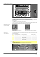
Program sequence indicator Type Serie V~ c/s V~ LANDIS & GYR 4A 3 5 6 7 10 11 17 20 ts Hz s VA 2A 21 22 t1 = 8...63 s 30 A B E G 1 2 (1) 40 C F 3 7161p02/0102 The program sequence indicator shows the respective startup position. The letters correspond to those given in the sequence switch diagram beside the viewing window. The numbers give the remaining prepurge time.
Settings and adjustments on the burner control Loosen all 6 screws and remove the cover of the LAE1...
Connection diagram Unit fuse 6.3 A (slow) in the current path between terminal 1 and relay contact «br...» is not shown. EK2 SB EK1 VIII VIII W NTC z LP R P FR LK N N M M1 UL3 I II IV VII IV I UL2 III AR V VI UL1 SM BR 7161a01/1010 N OV1 (OV) M2 OV2 OV3 M Legend AR BR EK1 EK2 FR L1 L2 LF LK Load relay with contacts «ar...» Lockout relay with contacts «br...» Lockout reset button on the LAE1...
Time diagram of sequence switch The maximum permissible afterburn time is 7 seconds – from the start of «t6». Customer-specific presettings of the times on request! a b I 81 a b II TSA III 79 89 a b IV 67 t4 V t3´ t9 86 t5 a b VI 93 t3 VII 70 a b VIII 3 a b IX t7 X t10 a b XI 66 a b XII t1 a b XIII t11 63 7161d01/1098 t12 t6 t8 T Legend T TSA t1 t3 t3´ t4 t5 120 s 0...9 s 8...
Connection examples Connection diagram and sequence program for operation with long preignition and repetition (actuator control checked, no load control). * When using an air pressure switch «LP», the connections between terminals 3 and 4 and 8 and 18 are not required Repetition UL.3 Repetition 2 13 14 15 16 12 19 18 1 LAE1 8 9 UL.
Connection examples (cont’d) Connection diagram and sequence program for operation with short preignition and without repetition. Ignition of main burner with light oil pilot burner (on / off control with checked actuator control).
Connection examples (cont’d) Connection diagram for modulating burner control with checked actuator control. Burners designed for modulating burner control also use the devices of the temperature or pressure control loop, in addition to the standard burner control equipment.
Legend AR BR BS c... d... DK e... EK1 EK2 FR FW H L L1 L2 LF LK LP M... NTC OV... (OV) R RV SB SM UL1 UL2 UL3 W Z Load relay with contacts «ar...» Lockout relay with contacts «br...» Operation switch Fan contactor with contacts «c...» Auxiliary relay with contacts «d...» Push-button Thermal overcurrent release Lockout reset button on the LAE1... (do not press «EK1» for more than 10 s!) Remote lockout reset button (do not press «EK2» for more than 10 s!) Flame relay with contacts «fr...
Dimensions Dimensions in mm LAE1... LAE1... AGG41041713 (AE) AGG11.1 81.9 A A B A A C C C To remove the LAE1... from its plug-in base, it is merely necessary to loosen the 4 screws «A». To remove the unit cover, also loosen the 2 screws «B». Legend C SG EK Elongated holes for fixing the plug-in base Viewing window Lockout reset button 2018 Siemens AG Building Technologies, Berliner Ring 23, D-76437 Rastatt Subject to change! 17/17 Building Technologies CC1N7161en 21.08.