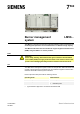
7 560 LMV6… Burner management system The LMV6 is a microprocessor-based unit with matching system components for controlling and supervision of forced draft burners of medium to large capacity. The LMV6 and this data sheet are intended for original equipment manufacturers (OEMs) using the LMV6 in or on their products. Notes Attention! All the safety, warning, and technical notes given in the basic documentation for the LMV6 (P7560) also apply to this document in full.
Features Burner control Electronic ratio control Gas pressure switch valve proving Flue gas recirculation (FGR) Fault status messages counter Error history Separate restart counter for each fuel Program stop function Forced intermittent operation (can be deactivated) Low-fire load shutdown Alarm in case of start prevention Parameterizable program times and functions The following items are integrated into the LMV6: Burner control complete with valve proving system Plug-in space
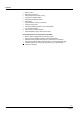
Supplementary documentation Product type Designation Documentation type Documentation number LMV60.110A2 Burner management system User Documentation A7560.1 LMV6 Burner management system Environmental Product Declaration E7560 *) LMV60.
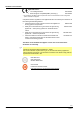
Standards and certificates Applied directives: Low Voltage Directive 2014/35/EU Electromagnetic compatibility EMC (immunity) *) 2014/30/EU *) The compliance with EMC emission requirements must be checked after the burner management system is installed in equipment Compliance with the regulations of the applied directives is verified by the adherence to the following standards/regulations: Automatic burner control systems for burners and appliances DIN EN 298 burning gaseous or liquid fuels S
Open Source Software (OSS) declaration Due to the license terms of the software we use, Siemens AG wishes to note that the OEM is obligated to provide the following license text for the end user in the documentation: Open Source Software (OSS) declaration Embedded in – or bundled with – the LMV6 are open source software (OSS) components and other third-party components identified below. You will find the specific product type and the valid version in the OSS document. Title: Readme_OSS System LMV6 V01.
Lifetime The LMV6 has a designed lifetime* of 250,000 burner startup cycles which, under normal operating conditions in heating mode, corresponds to approx. 10 years of service (starting from the date of manufacture on the nameplate). This is based on the endurance tests specified in the EN 298 standard. A summary of the conditions has been published by the European Control Manufacturers Association (Afecor) (www.afecor.org).
Type summary Burner management system The LMV6 is a microprocessor-based burner control with coordinated system components for controlling and monitoring forced draft burners of medium to large capacity. Without With ● --- --- --- EU Mains voltage --- Parameter set (country specific) 3 With O2 control --- Temperature compensation With load controller ● With flue gas recirculation (FGR) With variable speed drive LMV60.110A2 Max.
Technical data Basic unit LMV6 Mains voltage 230 V AC -15% / +10% Mains frequency 50 Hz 6% External primary fuse (Si) Max. 6.3 A, slow Caution! Risk of damage to the switching contacts! If the external primary fuse (Si) or internal fuse (F1) is blown due to overload or short-circuit at the terminals, the LMV6 must be replaced.
Technical data (continued) Terminal loading: Inputs Mains supply: The input current for the power supply is dependent on the operating status of the LMV6 Rated voltage UMains 230 V Safety shutdown from the operating position at mains voltage ≤ 185 V AC Restart is initiated when mains voltage exceeds ≥ 195 V AC Status inputs (with the exception of the safety loop) of the contact feedback network are used for system supervision and require mains-related input voltage Safety loop Refer to Term
Technical data (continued) Terminal loading: Outputs Total contact loading: Rated voltage 230 V AC, 50 Hz LMV6 input current and safety loop Max. 5 A Note! The input current at terminal X93 pin 5 also flows through safety loop terminal X93 pin 1 / pin 2. Fusing is provided via the unit fuse (F1) of the LMV6.
Technical data (continued) Cable lengths Mains supply line Max. 100 m (100 pF/m) Fan motor Max. 50 m (100 pF/m), unshielded Pressure switch valve proving Max. 50 m (100 pF/m), unshielded Remote lockout reset (laid separately) Max. 50 m (100 pF/m), unshielded Alarm Max. 50 m (100 pF/m), unshielded Air pressure switch Max. 50 m (100 pF/m), unshielded Safety loop Max. 50 m (100 pF/m), unshielded Ignition transformer Max. 50 m (100 pF/m), unshielded Gas pressure switch-max Max.
Technical data (continued) RAST3.5 connector Mechanical data Connection cross sections, conductor screw connection RAST5 connector Mechanical data Stranded conductor, fine-wired (flexible) Cross section Min. 0.14 mm² Max. 1.5 mm² Stranded conductor, fine-wired (flexible) with ferrule Cross section Min. 0.25 mm² Max. 1 mm² Stripping length Approx. 7 mm Screw tightening torque 0.
Technical data (continued) Environmental conditions Storage EN 60721-3-1 Climatic conditions Class 1K3 Mechanical conditions Class 1M2 Temperature range -20 to +60°C Humidity < 95% r.h. Transport EN 60721-3-2 Climatic conditions Class 2K3 Mechanical conditions Class 2M2 Temperature range -20 to +60°C Humidity < 95% r.h. Operation DIN EN 60721-3-3 Climatic conditions Class 3K3 Mechanical conditions Class 3M2 Temperature range -20 to +60°C Humidity < 95% r.h.
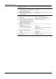
Technical data (continued) Flame supervision with ionization probe With LMV6 at terminal X52. Warning! Provide protection to prevent people from coming into contact with the ionization probe (risk of electric shock)! Short-circuit current Max. AC 850 µA Permissible length of flame detector cable (laid separately) 10 m (100 pF/m), unshielded Note! Display on the AZL66 in the event of a short-circuit! In the event of a short-circuit, a flame signal of 12% is displayed on the AZL66.
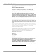
Technical data (continued) Connection diagram Measuring circuit for detector current measurement Ionization probe Legend C Electrolytic capacitor 100 to 470 µF; 10 to 25 V DC ION Ionization probe M Micro-ammeter Ri max.
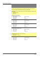
Technical data (continued) Flame supervision with QRA2 / QRA2M / QRA4 / QRA10 Caution! If QRA2 / QRA2M / QRA4 / QRA10-UV tubes are used for flame supervision on the LMV6, it must be ensured that the LMV6 is permanently connected to power (EN 298), thus enabling the LMV6 to detect flame detector failures during startup and shutdown. The LMV6 generally operates with QRA flame detectors in intermittent operation.
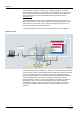
Assignment of terminals 17/20 Smart Infrastructure CC1N7560en 3/4/2020
Legend AL Alarm device FGR Flue gas recirculation Lockout reset button (info button) /reset (EK1) ION Ionization probe LP Air pressure switch LR Load controller LR-OPEN Load controller OPEN position LR-CLOSED Load controller CLOSED position M Fan motor P LT Pressure switch valve proving Pmax Pressure switch-max Pmin Pressure switch-min PV Pilot valve QRA UV flame detector SK Safety loop V1 Fuel valve V2 Fuel valve Z Ignition transformer 18/20 Smart Infrastructure CC1N756
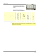
Dimensions Dimensions in mm LMV60.
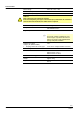
Dimensions (continued) Dimensions in mm 77 7560m08/0519 AGG6.