
User Manual

10/20
Smart Infrastructure CC1N7560en
3/4/2020
Technical data (continued)
Total contact loading:
Rated voltage
230 V AC, 50 Hz
LMV6 input current and safety loop
Max. 5 A
Note!
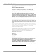
The input current at terminal X93 pin 5 also flows through safety loop terminal X93
pin 1 / pin 2. Fusing is provided via the unit fuse (F1) of the LMV6.
The components of the safety loop disconnect the energy supply to the following loads
when tripped:
Ignition transformer
Fuel valves
Individual contact loading:
Fan motor (M) terminal X72 pin 4
Rated voltage
230 V AC, 50 Hz
Rated current
2 A
Power factor Cos 0.4
Alarm (AL) terminal X92 pin 2
Rated voltage
230 V AC, 50 Hz
Rated current
1 A
Power factor
Cos 0.6
Ignition transformer (Z) terminal X82 pin 3
Rated voltage
230 V AC, 50 Hz
Rated current
2 A
Power factor Cos 0.2
Fuel valve (V1) terminal X84 pin 3
Fuel valve (V2) terminal X91 pin 4
Rated voltage
230 V AC, 50 Hz
Rated current
2 A
Power factor Cos 0.4
Note!
With activated valve proving via fuel valve circuit
Rated current 1 A
Power factor Cos 0.4
Pilot valve (PV) terminal X83 pin 3
Rated voltage
230 V AC, 50 Hz
Rated current
1 A
Power factor Cos 0.4
Terminal loading: Outputs