7 LOA2... 118 LOA3... Oil Burner Controls LOA2... LOA3... Oil burner controls for the supervision, startup and control of 1- or 2-stage forced draft oil burners in intermittent operation. Oil throughput of less than 30 kg/h. The LOA2... / LOA3... and this Data Sheet are intended for use by OEMs which integrate the oil burner controls in their products. Use, features The LOA... are used for the startup, supervision and control of 1- or 2-stage forced draft oil burners in intermittent operation.
Warning notes To avoid injury to persons, damage to property or the environment, the following warning notes must be observed! Do not open, interfere with or modify the unit! All activities (mounting, installation and service work, etc.) must be performed by qualified staff Before making any wiring changes in the connection area, completely isolate the plant from mains supply (all-polar disconnection).
Installation notes Always run high-voltage ignition cables separately while observing the greatest possible distance to the unit and to other cables Make absolutely certain that live and neutral conductors are correctly connected to terminals 1 and 2 of the burner control Install switches, fuses, earthing, etc.
Commissioning notes When commissioning the plant, when carrying out maintenance work, or after longer off periods, make the following safety checks: Safety check to be carried out Anticipated response a) Burner startup with flame detector darkened Lockout at the end of «TSA» b) Burner startup with flame detector exposed to extraneous light Lockout after approx. 40 seconds c) Simulation of flame failure during operation.
Life cycle Burner controls has a designed lifetime* of 250,000 burner startup cycles which, under normal operating conditions in heating mode, correspond to approx. 10 years of usage (starting from the production date given on the type field). This lifetime is based on the endurance tests specified in standard EN 230. A summary of the conditions has been published by the European Control Manufacturers Association (Afecor) (www.afecor.org).
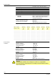
Type summary The type references given in the table refer to oil burner controls with no plug-in base and no accessories. For ordering information for plug-in bases and other accessories, see Accessories. Article no. Type Main voltage Undervoltage detection Times in seconds t1 t3 min. approx. TSA max. t3n approx. t3n‘ approx. t4 approx. Replacement types Standard version BPZ:LOA24.171B27 LOA24.171B27 AC 220 V ● 13 13 10 20 --- 20 LMO14.111C2 LMO24.111C2 BPZ:LOA24.171B17 LOA24.
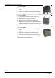
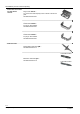
Test adapter (must be ordered separately) Test adapter KF8833 For checking the functions of burner controls on the burner With signal lamps for program indication With one pair of jacks for measuring the flame detector current Test adapter KF8840 For checking the functions of burner controls on the burner With signal lamps for program indication With on / off switch for simulating the flame signal With holes for checking the control voltages at the tabs of the burner control With one pair o
Accessories (must be ordered separately) Connection accessories for small burner controls Plug-in base AGK11… To connect the small-capacity burner controls to the burner plant. See Data Sheet N7201 Cable holder AGK66… For plug-in base AGK11. See Data Sheet N7201 Cable holder AGK65… For plug-in base AGK11. See Data Sheet N7201 Flame detectors Photoresistive detectors QRB... See Data Sheet N7714 Frontal illumination: Blue-flame detectors QRC...
Accessories (must be ordered separately) Actuators Actuator SQN3... See Data Sheet N7808 Actuator SQN7... See Data Sheet N7804 Actuator SQN9... See Data Sheet N7806 Adapters / replacement types No rewiring required Adapter KF8819 For replacing LAB1... / LAI... by LOA... No rewiring of plug-in base required Others Remote reset module ARK21A27 For use with the LOA26... / LOA36... printed circuit board versions 9/16 Building Technologies Division CC1N7118en 19.05.
Technical data General unit data Mains voltage AC 220 V –15 %...AC 240 V +10 % AC 100 V –15 %...AC 110 V +10 % 50...60 Hz ±6 % Max. 10 A (fast) Approx. 3 VA Optional IP40, must be ensured through mounting I (burner control with plug-in base) Mains frequency External primary fuse (Si) Power consumption Perm. mounting position Degree of protection Safety class Input current to Terminal 1 Terminal 3 Perm. cable lengths - Detector cable laid separately - Remote reset laid separately Weight Perm.
Flame supervision Flame supervision with QRC... Measuring circuits and length of the detector cables in accordance with Data Sheet N7716. QRC... (typically) Type of burner control Detector current Permissible detector required during current during the Possible detector current in operation operation prepurge time (dark (with flame) current) LOA24.171B17 Min. 70 µA Max. 5,5 µA Max. 90 µA LOA24.171B27 Min. 70 µA Max. 5,5 µA Max. 110 µA LOA24.173A27 Min. 45 µA Max. 5,5 µA Max.
Flame supervision Flame supervision with QRB... Measuring circuits and length of the detector cables in accordance with Data Sheet N7714. QRB... (typically) Detector current Type of burner control required during operation (with flame) Permissible detector current during the Possible detector prepurge time (dark current in operation current) (with flame) (without flame) LOA24.171B27 / LOA24.171B17 LOA25.173C27 Min. 70 µA Max. 5.5 µA Max. 210 µA LOA24.173A27 Min. 45 µA Max. 5.5 µA Max.
Function The relevant function diagram shows the required or permissible input signals to the control section and to the flame supervision circuit hatched (refer to Connection diagrams). If these input signals are not present, the burner control will stop the startup sequence to trigger lockout where required by safety regulations.
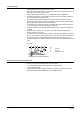
LOA24.171B27 LOA24.171B17 tz2 EK1 L1 x tz1 fr y z Control sequence 7118a06/1004 Connection diagram inclusive internal diagram c d f g e a b A R A´ SB W B C D 1 8 OH FR K V 3 OW t3n 1 2 TZ 3 8 10 7 6 5 4 11 9 t1 tw SB 6 Z t3 OW W 7 TSA BV1 R 5 BV2 Z AL N Si 4 t4 QRB OH BV1 11 FS M BV2 QRC bl N LOA24.
LOA26.171B27 tz2 EK1 tz1 fr y z x L1 a With ARK21 Control sequence 7118a08/1004 Connection diagram inclusive internal diagram e f g cd FR b A R A´ SB W B C D 1 OH K 8 V remote lockout OW reset module 3 t3n TZ 1 2 8 10 3 7 6 5 4 9 11 12 3 M SB t1 tw Z OW W R QRB OH SA N Si SA Z AL bl 10 10 13 14 1 QRC 4 t4 sw BV2 2 TSA BV1 M N 9 7 t3 BV1 N L 6 5 BV2 br 11 FS EK2 12 7118d05/0402 LOA36.
Dimensions LOA... 9 7118m06/0205 62,5 22 5,5 Dimensions in mm 88 Plug-in base AGK11... 41,5 91 62,5 47 22 47 LOA3... 62,5 LOA2... 7118m07/1004 36,5 Status indication (orange) Indication of flame strength (green) >83,5 67,5 >66 >23 >12 50 Remote lockout reset module ARK21A27 Remote lockout reset module for use with the LOA26... / LOA36... Printed circuit board with no housing.