
User Manual


3/16
Building Technologies Division CC1N7118en
19.05.2016
Installation notes
Always run high-voltage ignition cables separately while observing the greatest
possible distance to the unit and to other cables
Make absolutely certain that live and neutral conductors are correctly connected to
terminals 1 and 2 of the burner control
Install switches, fuses, earthing, etc., in compliance with local regulations
Ensure that the maximum permissible current load for the connecting terminals is
not exceeded (refer to Technical data)
Do not feed external mains voltage to the control outputs of the burner control.
When testing the function of devices controlled by the burner control (fuel valves or
similar), the burner control must not be connected
To disconnect the unit from the mains, a complete shut-down must be carried out
under overvoltage category III conditions in each pole
Secure the earthing lug in the terminal base with a metric screw and a lockwasher
or similar
Switches, fuses, earthing, etc., must be in compliance with local regulations;
primary fuse max. 10 A (fast)
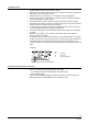
For safety reasons, feed the neutral conductor to the neutral distributor in the plug-
in base, or to terminal 2. Connect the burner components (fan, ignition transformer
and fuel valves) to the neutral distributor as shown in the figure 7435a14. The
connection between the neutral conductor and terminal 2 is prewired in the terminal
base
Example
2
37 4 5
M
N
7435a14/0601
Z
V1
V2
Key
Vx Fuel valve
M Fan motor
Z Ignition transformer
Correct wiring of neutral conductors!
Electrical connection of flame detectors
It is important to achieve practically disturbance- and loss-free signal transmission:
Never run the detector cable together with other cables
– Line capacitance reduces the magnitude of the flame signal
– Use a separate cable
Observe the permissible lengths of the detector cables, see Technical data and
Data Sheet / Flame detector QRB (N7714) and QRC (N7716).