
User Manual


4/14
Siemens Energy Manager / Heating Conroller RVP540 / RVP550 CE1N2488en
Building Technologies 04.11.2009
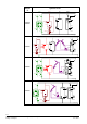
Automatic d.h.w. heating
D.h.w. heating on / off
Manual operation on / off
Manual operation on / off
“Green“ operation on / off
In this operating mode, all nonrenewable forms of energy are unavailable and
locked. Heat demand is covered exclusively by the wood-fired boiler and the
solar collectors. Comfort losses, if any, will be accepted.
Frost protection is ensured in all operating modes.
Ordering
When ordering, please give type reference RVP540 or RVP550. Sensors and room
units, actuators and valves, if required, are to be ordered as separate items.
Equipment combinations
• Flow, return, d.h.w. and solar panel temperature:
− All types of sensors using an LG-Ni 1000 sensing element
− Strap-on sensor QAD22
− Immersion sensors QAE22… or QAP21.2
• Outdoor temperature:
− Outside sensor QAC22 (sensing element LG-Ni 1000)
− Outside sensor QAC32 (sensing element NTC 575)
• Flue gas temperature:
− Flue gas temperature sensor FGT-PT1000 (range of use up to 400 °C)
• Room temperature:
− Room unit QAW50
− Room unit QAW70
− Room sensor QAA10
The following types of actuators from Siemens HVAC Products can be used:
• 3-position actuators with running times from 0.5 to 14.5 minutes
• 2-position actuators
• Operating voltage AC 24…230 V
Communication is possible:
• With all LPB-compatible devices supplied by Siemens HVAC Products
• With the SYNERGYR OZW30 central unit (software version 3.0 and higher)
• Via the point-to-point interface (PPS) with BMU and the room unit
Conduit box AGS2S.200/109 featuring surge protection (protects solar panel sensor B6
or B61 against surges resulting from lightning).
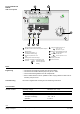
The configuration tool, which is available on CD, enables you to easily find the applica-
tion you want. The tool delivers the basic plant diagram number, the terminal assign-
ments and the list with the major configuration parameters.
There is no direct connection from the tool to the controller, which means that configu-
rations cannot be uploaded or downloaded. To select the required type of plant, con-
figuration parameters no. 100 through 195, which can be printed out by the configura-
tion tool, must be adopted.
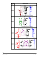
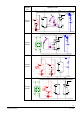
The following pages show a number of examples out of a choice of more than 500
basic plant diagrams.
Suitable sensors and
room units
Suitable actuators
Communication
Surge
protection
Tool