
User Manual


9/14
Siemens Energy Manager / Heating Conroller RVP540 / RVP550 CE1N2488en
Building Technologies 04.11.2009
For detailed information about installation, technical design, functions and data bus
(LPB), refer to the following pieces of documentation:
• Installation Instructions RVP540, RVP550: CE1G2488en
• Basic Documentation RVP540, RVP550: CE1P2488en
• Configuration and Application Manual for one or two Heat Sources, RVP540,
RVP550: CE1P2489en
• Configuration and Application Manual for three Heat Sources, RVP550:
CE1P2490en
• Data Sheet “Basic System Data LPB“: CE1N2030E
• Data Sheet LPB: CE1N2032E
• Data Sheet “Installation of Heating Plant in Compliance with EMC Directives“
CE1N2034E
Mechanical design
The RVP5xx consists of controller insert with the electronics, power section, output
relays and – on the unit front – all operating elements, and base with the connection
terminals. The operating elements are located behind a cover.
The operating instructions are inserted in the cover.
The controller insert is secured to the base with 2 screws.
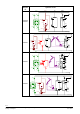
The RVP5xx can be fitted in 3 different ways:
• Wall mounting (on a wall, in the control panel, etc.)
• Rail mounting (on a standard mounting rail)
• Flush panel mounting (control panel door, etc.)
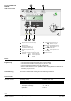
• Buttons for selecting the operating mode
• Buttons for d.h.w. heating ON / OFF
• Setting knob for manual room temperature readjustments
• Button for manual operation
• Button for “green“ operation
• Info button
Entry or readjustment of all setting parameters, activation of optional functions and
reading of actual values and operating states is made based on the operating line prin-
ciple. An operating line with the associated number is assigned to each parameter,
each actual value and each function that can be selected.
One pair of buttons is used to select the operating line and one pair to readjust the
display.
Additional
documentation
Analog operating
elements
Digital operating
elements