
Data Sheet for Product

5/6
Building Technologies SYNERGYR
®
Control and billing system CE1N2803en
HVAC Products For service and replacement – system overview 04.01.2005
Engineering notes
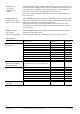
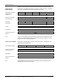
Selection of the components required is made with the help of the following tables.
Replacement of the WRV81 / WRV84 by a Siemeca™ M-bus heat meter, a motorized
zone valve, a mounting kit and a control and heat meter interface.
200 l/h 400 l/h 750 l/h 1,500 l/h
up to 1,000 l/h above 1,000 l/h
WFQ21.D081 WFM21.E131
WFZ.MBUSSET
VVP47.10-0.63 VVP47.10-1.6 VVP47.20-4.0 / VVP45.20-4.0 VVP45.20-10
ALG10/20 --- spec.
SSP81 for VVP47… / SSB81 for VVP45…
ALG80WRI (collector, fitting, seals, immersion pocket)
WRI80
If, up to now, the adjusting screw has not been fully opened, the components for “up to
1,000 l/h“ can also be used for design flow rates above 1,000 l/h. In that case, the ad-
justing screw must be appropriately opened.
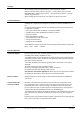
Replacement of the WRV83 by a Siemeca™ M-bus heat meter, a mounting kit and a
control and heat meter interface.
200 l/h 400 l/h 750 l/h 1500 l/h
WFM21.B111 WFM21.D111
WFZ.MBUSSET
ALG83WRI (fitting, immersion pocket)
WRI80
If flow limitation is required, “Replacement for WRV81“ must be selected since flow
limitation takes place via the zone valve.
Replacement for
WRV81 / WRV84
Nominal flow rate WRV
Design flow rate
of apartment
Siemeca™ heat meter
Connecting cable
Zone valve
Mounting kit
A
ctuator
Mounting kit
Control and heat meter
interface
Note
Replacement for WRV83
Nominal flow rate WRV
Siemeca™ heat meter
Connecting cable
Mounting kit
Control and heat meter
interface
Note