CRAP-B Nuclear power station Planning of fire detection systems Document no. €593 Edition 03.
%census ESE kRl R e R3S 3.
Cerberus o593 II 3.88 3.2 Summary of fire protection procedures 16 3.2.1 Reactor safety building 16 3.2.2 Ancillary reactor system building (rad waste) 17 3.2.3 Switch gallery building (operations building) 18 3.2.4 Rower house 13 3.2.5 Emergency power generator building 20 3.2.6 Steam generator building 20 3.2.7 Outgoing transformers 20 3.3 Detailed solutions 21 3.3.1 Main coolant pump 21 3.3.2 0il supply rooms of the main coolant pumps 21 3.3.3 Main operating platform 22 3.3.4 Ring room 22 3.3.
Cerberus 2593 1 1. General 1.1 Introduction These guidelines cover the peculiar characteristics to be taken into con-~ consideration in the planning of fire detection systems for nuclear power stations. They supplement the documents of the other indices in the CRP fire detection systems' manual. National guidelines and regulations have priority over the Cerberus guidelines.
CERBERUS €593 2 1.4 Differentiating between the various reactor types Heat is generated by inducing heavy uranium nuclei to fission. Nuclear power stations differ in the method by which this heat is employed to generate steam which in turn drives the turbines. 03.
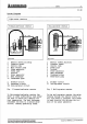
CERBERUS System diagrams @883 3 03.88 Light-water reactors Pressurized-water reactor Rolling-water reactor I Primary circuit II Secondary circuit IIT Cooling-water circuit Fig. 2 Pressurized-water reactor In the pressurized-water reactor the water is under sufficiently high pressure that it cannot boil despite the high temperature. The heat exchange transfers the heat to a second water circuit, thereby generating steam.
%CERBERUS 593 4 reactor 03.
e593 5 03.88 Graphite reactors Gas-cocked reactor Soviet RB line I Primary circuit {(gas circuit) II Secondary circuit (Water and steam circuit) III Cooling-water circuit Fig. 6 Gas-cooled graphite reactor A gaseous coolant is used instead of a liquid coolant. The steam generator is located in the same pressure vessel as the reactor.
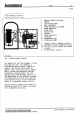
%CERBERUS e593 & Fast-breeder reactor 03.88 ME1426CR Reactor safety building Reactor Circulating pump Heat exchange Steam generator building Steam generator Steam pipe Machine hall Turbine Power generator Condenser Condensate pipe Condensate pump Primary circuit {Sodium circuit) Secondary circuit (Sodium circuit) Tertiary circuit (Water and steam circuit) Cooling-water circuit Fig. 8 Fast-breeder reactor The reactor of the fast-breeder is very much smaller than, for example, a pressurized-water reactor.
CERBERUS e593 7 1.5 Current exploitation of nuclear power In 1985 nearly 400 nuclear power plants in 26 countries produced around 15% of the worldwide electrical power. Fig. 9 shows the nuclear power station capacities installed in the various countries as of the beginning of 1986. GW Number of blocks Usa 83,0 98 France 38,9 44 USSR 28,6 51 Japan 23,6 33 W-Germany 16.
Functional organization of the buildings The functional organization and the designation of the buildings varies, depending on the manufacturer. and the type of reactor., This means that they can deviate from the designations and illustrations used in this handbook. Reactor safety building The nuclear installations with the reactor are located in the reactor safety building.
¢ CERBERUS 2. Fire protection planning 2.1 Special features of nuclear power station Nuclear safety Ensuring the nuclear safety of the nuclear power station has top priority. This includes controlled shutdown and adequate after cooling of the reactor in the event of a fire. For this reason, redundant installations of all vital systems are available in separate rooms that are protected by fire walls. This important compartmentalization may be missing in older nuclear power stations.
593 10 Sodium cooling for fast-breeder reactors Sodium oxidizes readily when it comes in contact with atmospheric humidity. The rupture of a sodium cooling line in the steam generator building can cause severe damage. For this reason steps must be taken to prevent sodium leaks and fires in the secondary sodium systems. Certain rooms are rendered inert. In other rooms, sodium leaks can be detected by the fire detection system (smoke detector) which means that the criterion "leak before break" is satisfied.
Cerberus 2593 11 2.
%CERBERUS 593 12 3. Planning of fire detection systems 3.1 General 3.1.2 Requirements The planning of a fire detection system for a nuclear power station is a soph— masticated task and should be assigned only to a planning team who is experienced in the planning and implement-— ration of fire detection systems. Direct cooperation with the nuclear power station’s experts responsible for fire protection and with the authorities is essential.
593 13 3.1.6 Selecting the fire detectors Fire detectors of the system MS9 should basically be selected. Because their functions are adjustable, these smoke detectors can be matched to the par— titular requirements and ambient conditions. Nuclear power stations contain numerous electrical risks that should preferably be detected with a mixed system of ionization and scattered-light smoke detectors.
}Cerberus 593 14 EEK— 03.88 3.1.11 Examples of a C8100 system configuration to be installed outside the controlled zone Fire detection/ v extinguishing system control units EVALUATION outside the safety building = ca too in the ancillary reactor building in the switch gallery building in the ancillary Bh Thee buildings v 3 Systemic. control Tats ACERBATE EXTERNALS ME1387CR Fig. 13 Example of a €S100 system configuration 1.
;CERBERUS 593 135 3.1.12 Fire control operation Automatic fire control operations can be initiated directly from the local sector terminal or from the addressable control elements in the detector line. 3.1.13 Controlling stationary extinguishing systems Cross-zoning is essential for automatic control of extinguishing systems. Local activation of the extinguishing system should be possible in all cases.
%CERBERUS 6593 16 03.88 3.2 Summary of fire protection procedures . The following summary can be used differently, depending on the type of Legend: nuclear power station and its manufacture— F detector = Ionization smoke detector true. It is based cn experience in R detector = Scattered-light smoke monitoring pressurized and beilingdetector water reactor plants with fire detect— D detector = Heat detector son systems. S detector = IR flame detector FPK = Alr sampling chamber BMA = Fire detection system 3.2.
%CERBERUS e593 18 03.88 3.2.3 Switch gallery building {operations building Utilization Detection, Stationary {Control of |[Supple|Comments detector type ing system ping system [measures Control center F + R detectors Halon 1301 BMA and possibly mixed monitoring |system ancillary room Cable braiding F + R detectors Hale 1301 BMA ruin (below control system center) Rooms with Room monitoring Principally control system F detectors electrical risks (control cabinets) |add.
CERBERUS @593 20 03.88 3.2.5 Emergency power generator building Utilization Detection, Stationary [Control of |Supple|Comments detractor type ing system ping system |measures Diesel generator F + § detectors {Deluge BMA * if the Diesel generator is system not Located in a separate * building ar fire compartment. Fig. 18 Defensive fire detection measures 3.2.
%CERBERUS 3.3 petaled solutions Some detailed solutions of typical nuclear power stations are outlined plow. Their applicability depends on the type of reactor.and on the manufacture. 3.3.1 Main coolant pump The main coolant pumps of the primary circuit are vital for cooling the reactor. For each pup one deluge system is . recommended which should be activated by cross-zoned ionization smoke detectors and flame detectors. A TV camera is recommended to supplement the fire detection system.
Cerberus 3.3.3 Main operating platform Due to the exceptional height of the containment, the main operating plat— form should be monitored with flame detectors and linear smoke detectors. Because the main operating platform is normally not accessible when the power station operates productively, video cameras are very useful for visually e593 22 03.88 verifying incoming alarms. The siting of such cameras should be determined in consultation with the operations management of the nuclear power station.
CERBERUS €593 23 3.3.5 Rooms with control cabinets in the switch gallery building Because some of these rooms can be fairly high, equipment monitoring may be necessary in addition to room monitoring. Without efficient countermeasures, fires in this building can seriously affect the nuclear safety, i.e. the control over the reactor and the productive capacity of the power station.
%CERBERUS Alternatively, smoldering fires can also be detected by arranging the monitoring beam of a linear smoke detector directly above the equipment. MN14Z8CR Fig. 27 Equipment monitoring with linear smoke detector 3.3.6 Cable braiding room The cable braiding room below the control center is a particular risk. Because of the enormous cable connect— ration, manual intervention is extremely difficult if a fire breaks out.
Cerberus e593 25 3.3.8 Activated carbon filters Because of their high fuel contribution in the event of a fire, activated carbon filters must be given special attention. The supply air and the exhaust air must be monitored for the presence of smoke particles. In the event of a fire, the supply air is automatically shut off so that hot combustion gases cannot ignite the carbon. A heat sensor is recommended in addition to the smoke detector 80 that a deluge system can be activated when both detectors respond.