Cerberus® CS1140 Fire detection system Planning EP7F Fire & Security Products Siemens Building Technologies Group
Data and design subject to change without notice. / Supply subject to availability. E Copyright by Siemens Building Technologies AG Wir behalten uns alle Rechte an diesem Dokument und an dem in ihm dargestellten Gegenstand vor. Der Empfänger anerkennt diese Rechte und wird dieses Dokument nicht ohne unsere vorgängige schriftliche Ermächtigung ganz oder teilweise Dritten zugänglich machen oder ausserhalb des Zweckes verwenden, zu dem es ihm übergeben worden ist.
About this document . . . . . . . . . . . . . . . . . . . . . . . . . . . . . . . . . . . . . . . . . . . . . . 1 1 1.1 1.1.1 1.1.2 1.1.3 1.2 Safety regulations . . . . . . . . . . . . . . . . . . . . . . . . . . . . . . . . . . . . . . . . . . . . . . . . . Signalwords and symbols . . . . . . . . . . . . . . . . . . . . . . . . . . . . . . . . . . . . . . . . . . . . Signalwords and their meaning . . . . . . . . . . . . . . . . . . . . . . . . . . . . . . . . . . . . . . . Symbols and their meaning . .
17 Range of cabinets H37... . . . . . . . . . . . . . . . . . . . . . . . . . . . . . . . . . . . . . . . . . . . 52 18 Range of cabinets H38... . . . . . . . . . . . . . . . . . . . . . . . . . . . . . . . . . . . . . . . . . . . 53 19 Range of cabinets H47... . . . . . . . . . . . . . . . . . . . . . . . . . . . . . . . . . . . . . . . . . . . 54 20 Range of cabinets H67... . . . . . . . . . . . . . . . . . . . . . . . . . . . . . . . . . . . . . . . . . . . 55 21 Range of cabinets H98... . .
32 32.1 32.2 32.3 32.4 32.5 Power supply . . . . . . . . . . . . . . . . . . . . . . . . . . . . . . . . . . . . . . . . . . . . . . . . . . . . . Power supply for the control unit . . . . . . . . . . . . . . . . . . . . . . . . . . . . . . . . . . . . . . Auxiliary power supply . . . . . . . . . . . . . . . . . . . . . . . . . . . . . . . . . . . . . . . . . . . . . . Operation with power supply from control unit . . . . . . . . . . . . . . . . . . . . . . . . . .
IV Fire & Security Products Siemens Building Technologies Group 05.
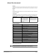
About this document Purpose This document describes the project planning of the hardware modules of the control unit CS1140. The consistent adherence to these instructions ia a prerequisite for a safe application. Scope This document contains information on all CS1140 components for EP7F, including part numbers for ordering.
Disregard of the safety regulations Before they are delivered, products are tested to ensure they function correctly when used properly. Siemens disclaims all liability for damage or injuries caused by the incorrect application of the instructions or disregard of warnings of danger contained in the documentation.
1 Safety regulations This chapter describes the danger levels and the relevant safety regulations applicable for the use of the Cerberus products. Please read the work instructions as well as the chapter ”About this document” thoroughly before beginning any work. 1.1 Signalwords and symbols 1.1.1 Signalwords and their meaning The danger level-that is, the severity and probability of danger-is indicated by the signal words listed below.
1.2 Safety-relevant working instructions Country-specific standards The products are developed and produced in compliance with the relevant international and European safety standards.
Modifications to the system design and the product Modifications to a system or to individual products may cause faults or malfunctioning. Please request written approval from us and the relevant authorities concerning intended system modifications and system extensions. Modules and spare parts D Locally procured modules and spare parts must comply with the technical specifications laid down by the manufacturer. This compliance is always ensured for original spare parts supplied by us.
6 Fire & Security Products Siemens Building Technologies Group e4595e 1 05.
2 Main features CS1140 Fire detection system for modular configuration min. 2000 detectors per CC1143; min. 700 detectors per CC1142; min.
3 Overview technical data CS1140 ±15% Operating voltage 115/230VAC 50...60Hz Power consumption 40...220VA (per converter B2F020) Battery operation in the event of mains failure – standard operating period – optional 12...24h up to 72h (see page 91) Environmental conditions Temperature during operation storage Humidity 0°C ... +40°C –20°C ... +60°C max.
4 Logical and physical structure In the CS1140 fire detection system, the logical structure is completely separated from the physical structure. This enables the greatest possible flexibility. Display and control terminal are based on the geographical and organizational aspects and are independent of the actual hardware installation of the detector network.
5 Bus systems In the CS1140 fire detection system there are 5 communication levels: I-Bus internal data bus between individual modules in the control unit (line modules, control modules etc.
Fire & Security Products Siemens Building Technologies Group Special feature Principle Scanning Network structure – – – Cerberus protocol – Cerberus protocol – collision detection – SPI/Motorola – Manchester coding serial Bus C-Bus cyclic, event controlled event-controlled, presence monitoring master/slave – – – master/master yes Short-circuit proof each user connected with line separator T-branch Loop line – Number of wires flat cable 26 2 (+3 wires for emergency operation) Number o
6 C-Bus stations The C-Bus network contains max. 16 stations (user connected) within the limits stated below (CC, CI, CT, CK) are any stations in any arrangement possible max. 64 AREAS DMS7000/LMS (management system) CERLOOP Control terminal CT11 Gateway CK11 (max.15) (max.15) C-Bus C-Bus network – max. 16 stations – 4 different types of stations – loop line max. 1400m with G51 ø 0.
6.3 Meaning of the suffix 41, 42, 43 Indicates the outline quantities (see chapter 7) respectively size of the equipped RAM: Cx1141 2x256Kx8Bit 2x512Kx8Bit 4x512Kx8Bit Cx1142 Cx1143 6.
6.5.3 ’CT11 Visualizer for Windows’ remote operation software Operating platform requirements in detail see document e6824 Supported control terminal types: B3Q460/48x/560/660/670/680/685/565 for details see also document e4940 and e5946 Standard control terminal Parallel control terminal CT/CI CA (RS232) V24 ....1000m E3I020 E3I020 max.
6.6 Logical AREAS CC CC 1 AREA CC AREA CI 2 3 4 5 7 6 CI 8 .. .. .. .. 61 62 63 64 CI All AREAS control terminal CK CK within one main CPU (’CI’ or ’CC’) max.
7 Outline quantities of C-Bus participants This chapter describes the quantitative limits of the various station types. Possibly performance related limitations depending on the outline quantities are not taken into account. For earlier EPs consult the corresponding release notes or the corresponding edition of this document, but use chapter 7.1.3, ’Maximum number of criteria in zone control 4 and 6 (RAM)’ of this document. The selection of the station type depends on the requirements.
7.1 Main CPU limits (CI/CC) The limits within the station types are given by hard- and software. Verify all given limits for each required station by going through this flow chart 7.1.1 Maximum number of devices (RAM) per station For the stationtypes CI1142, CC1142, CC1143, this limit is depending on the setup of the logical structure. The following graph allows to find this limit depending on the estimated average number of ELEMENTS per ZONE.
i Special structures now need to be counted equivalent to the following number of devices: Structure 7.1.2 Number of devices S D-Bus participants with an own D-Bus address (e.g. DOT1151, DO1131, DM1154, DCW1151, DOW1171...
Example: CI1142 with 150 control zones with an average of 9 control criteria. The point of intersection for the number of control zones (150) and the number of criteria per control zone (9) must be within the permitted range. Diagram ’Maximum ratings of controls’ CI1142 and CC1142 Number of criteria per control zone 16 criteria per control zone = max. 150 control zones 16 14 12 10 example 9 4 criteria (average) per control zone = max.
7.1.5 Maximum number of I-Bus-modules no ÁÁÁÁÁÁÁÁÁÁÁÁÁÁÁÁÁÁÁÁÁÁÁÁÁÁÁÁÁ ÁÁÁÁÁÁÁ ÁÁÁÁÁÁÁ ÁÁÁÁÁÁÁ ÁÁÁÁÁÁÁÁ ÁÁÁÁÁÁÁÁÁÁÁÁÁÁÁÁÁÁÁÁÁÁÁÁÁÁÁÁÁ Table ’Maximum number of I-Bus-modules’ select station with higher capacity or use an additional station Stationtype I-Bus modules number of I-Bus-modules
7.2 Control terminal limits (CT/CI) define the required number of control terminals by going through this flow chart 7.2.1 Maximum number of texts The number of texts of other stations (i.e. AREAS) that can be displayed on one control terminal (CT/CI) is limited.
7.3 Gateway limits (CK) check gateway configuration 7.3.1 Limits of the memory (RAM) use CK1143 type gateway stationtype CC1143 yes visible on CK ? no 7.3.2 CK1142: suited for CI1142, CC1142 stations EPROM set: ’CKQ00xxx’ RAM sets: 4x Z3S080 or 2x Z3S070 CK1143: suited for CI1142, CC1142, CC1143 stations EPROM set: ’CKW00xxx’ RAM sets: 4x Z3S070 (RAM upgrade necessary on E3H020) Limits of CERLOOP addressing Via one gateway a maximum of 8 C-Bus stations (CI/CC) can be addressed.
7.4 AlgoWorks utility programs limits 7.4.1 Limit of SmartHandy (SWE11-A) Limit of SmartHandy software The current SmartHandy software has a limitation of 2400 nodes, i.e. the total of all ELEMENTS, ZONES, SECTIONS and AREAS must not exceed 2400. Trying to open a station with more than 2400 nodes will produce the SmartHandy error message ’Too many DB records’ and the SmartHandy program will abort.
8 Specify hardware required In order to be able to specify the hardware required, system key data must be specified according the following procedure: 1. Specify number and type of detection lines dependent on: Detector series Number of detectors, input and output modules Building structure 2.
9 Choice of appropriate control unit cabinet For a suitable normal application, the required control unit cabinet can be worked out from the outline quantities for the main CPU. ÁÁÁÁÁÁÁ ÁÁÁÁÁÁÁ ÁÁÁÁÁÁ ÁÁÁÁÁÁÁ ÁÁÁÁÁÁ ÁÁÁÁÁÁÁ ÁÁÁÁÁÁÁ ÁÁÁÁÁÁÁ ÁÁÁÁÁÁ ÁÁÁÁÁÁÁ ÁÁÁÁÁÁ ÁÁÁÁÁÁÁ ÁÁÁÁÁÁÁÁÁÁÁÁÁÁÁÁÁÁÁÁÁÁÁÁÁÁÁÁÁÁÁÁÁÁÁÁÁÁÁÁ ÁÁÁÁÁÁÁÁÁÁÁÁÁÁÁÁÁÁÁÁ ÁÁÁÁÁÁÁ ÁÁÁÁÁÁÁÁÁÁÁÁÁ ÁÁÁÁÁÁ ÁÁÁÁÁÁÁ ÁÁÁÁÁÁÁÁÁÁÁÁÁÁÁ ÁÁÁÁÁÁ ÁÁÁÁÁÁÁÁÁÁÁÁÁÁÁÁÁÁÁ Type of station Cabinet H38G220 Cabinet H38G320 j J CI1142 CC1142 CC1143 Cabinet H47...
10 CI1142 in cabinet H38... (flat) H38G220 Component of Z3I470 H38G220: Set with – cabinet – door – module chassis – earth terminals 520 B2F020 B3Q... B3Q... 602 Z3I380 AX1210 H23B040 AX1210 H23B010 88 100* Connection for periphery * incl.
CT1142 (additional operating facilities) Details see page 42 C-Bus E3C011 B2F020 24V 24V Akkus AX1210 24V 5V E3G070 RS232 or K3I090 2 E3M... E3G... E3L... E3I040 1........7 1..2 24V 1 CI1142 I-Bus AlgoPilot B3Q...
11 CI1142 in cabinet H38... (deep) Component of Z3I470 H38G320: Set with – cabinet – door – module chassis – mains terminals 520 H38G320 B2F020 B3Q... B3Q... 602 Z3I380 H23B010 AX12.. H23B040 AX12.. B3Q321 B3R051 147 155* Connection for periphery * incl.
CT1142 (additional operating facilities) Details see page 42 C-Bus Mains B2F020 24V 24V 5V E3C011 24V RT = Remote transmission Akkus AX12.. CI1142 I-Bus AlgoPilot B3Q... E3G070 E3I020 RS232 1 1..2 or K3I090 24V B3R051 2 B3Q321 E3G... E3L... E3M... E3L030 1........
12 CI1142 in cabinet H47... H47G611: Set with – door – frame – module chassis – terminal blocks – mains terminals – battery supporting plate – relay rail 434 H47G611 Component of Z3I510 B3Q... B2F020 B3Q... 735 E3C011 Z1I060 or Z1I020 or Z1I030 B3Q321 H23B010 AX12.. H23B040 B3Q321 AX12..
CT1142 (additional operating facilities) Details see page 42 C-Bus Mains B2F020 24V 24V 5V E3C011 24V Akkus AX12.. CI1142 I-Bus AlgoPilot B3Q... E3G070 E3I020 RS232 1 Basic equipment Option RT = Remote transmission 1..2 or K3I090 24V B3R051 2 B3Q321 1........7 Z3B171 Fire control installation E3I040 LON-Bus RT 250VAC 10A for details see page 47 Printer internal or –> see page 82 Pager external printer –> see page 86 E3G... E3L... E3M...
13 CC1142/43 in cabinet H47... Module chassis H47... can also be built into 3rd party housings (see page 57) H47G601/611: Set with – door – frame – module chassis – terminal blocks – mains terminals – battery supporting plate – relay rail H47G611 434 H47G601 B2F020 B3Q... H23B010 735 E3X10. H23B040 Z1I060 or Z1I020 or Z1I030 B3Q321 B3R051 AX12.. AX12..
CT1142 (operation = separate C-Bus station) Details see page 42 Basic equipment Mains C-Bus Batteries AX12.. 24V CPU 24V Battery charging mdule I-Bus Driver E3I020 1..........8 24V or RS232 1 Z3B171 RT CC1142/43 B2F020 E3X10. 1..2 Option RT = Remote transmission K3I090 E3G... E3L... E3M...
Auxiliary power supply in second H47 housing ÒÒÒÒÒÒÒÒÒ ÒÒÒÒÒÒÒÒÒ ÒÒÒ ÒÒÒ ÒÒÒ ÒÒÒÒÒÒÒÒÒ ÒÒÒ ÒÒÒ ÒÒÒ ÒÒÒÒÒÒÒÒÒ ÒÒÒ ÒÒÒÒÒÒ ÒÒÒÒÒÒÒÒÒ ÒÒÒÒ ÒÒÒÒ ÒÒÒÒ 44 E3H020 + 2x Z1I030 43 45 52 37 Mains terminals Z3I450 47 48 Housing set H47G611 or H47E100 and H47T111 Details see page 54 E3... Z1I... E3... Z1I... Cable duct 34 35 36 max. 8 25 Z3I330 (diverse) Z3I330 (lines) B2F020 24 E3I020 Z1I030 E3L020 Z1I030 E3G050 Z1I030 E3... Z1I...
13.2 Cable sets for supplementary power supply in H47 housing The Z3I870 cable set can always be used for the wiring of the supplementary power supply. The cable set contains all the necessary cable and wires for connections to the next extension. CC1142/43 for H47E100 and H47E110 Z3I350 E3X10. E3X10. Z3I870 1st. extension E3C011 Z3I870 B2F020 2nd. extension E3C011 E3C011 E3C011 Z3I870 E3C011 3rd.
14 CC1142/43 in cabinet H67... H67G601/611: Set with – door – frame – module chassis – mains terminals – battery supporting plate – relay rail H67G611 434 H67G601 Z1I070 oder Z1I040 oder Z1I050 H67E101 Einschub aufsteckbar im Anschlussfeld B3Q... H23B010 B2F020 H23B040 1130 B3Q321 E3X10. B3R051 H H H H H H H H 300 Connection panel max.
CT1142 (operation = separate C-Bus station) Details see page 42 Basic equipment C-Bus Batteries AX12.. 24V CPU 24V Battery charging mdule I-Bus Driver E3I020 1..........8 24V or RS232 1 Z3B171 RT Option CC1142/43 B2F020 E3X10. 1..2 RT = Remote transmission Mains K3I090 E3G... E3L... E3M...
14.1 Installation possibilities on module chassis H67... Special feature: H67E100 has 3 different hole patterns for mounting. As a result, the relationship between connection block / modules / batteries can also be arranged differently Grid for modules Mounting variants AX1201 or AX1209 E3... Z1I... E3... Z1I... 62 65 (Battery 12V) (Battery 12V) AX1201 or AX1209 Modules E3... Z1I... E3... Z1I... AX1201 or AX1209 Connection panel Z3I330 max.
14.3 Combination possibilities H47 + H67 cabinet or H98 cabinet Details on module chassis: H67E101 see page 55 H47E100 see page 54 Z3G170 = 4x H67E101 H67E101 Profil rail on rear panel of H98G600 32 module spaces 3 battery sets 32 module spaces 5 universal brackets H47E100/110 H67E101 or H47E100/110 Note: The following modules can not be mounted on G1E010: – Z1I020....
14.
14.5 Cable sets for supplementary power supply The Z3I870 cable set can always be used for the supplementary power supply wiring. The cable set contains all the necessary cable and wires for connection to the next extension. CC1142/43 for H67E101 and H47E110 Z3I350 E3X10. Z3I870 1st extension E3C011 E3X10.
15 Control terminals AlgoPilot B3Q... There are two different series of control terminals to choose from. Mixing of standard- and comfort terminals in the same system is possible. Application region Comfort terminals Standard terminals B3Q660 B3Q460 International Nordic B3Q680 B3Q480 B3Q685 B3Q485 B3Q560 CH Asia/Pacific B3Q565 Australia B3Q670 France (special french application only) B3Q490 42 Fire & Security Products Siemens Building Technologies Group e4595e 15 05.
15.1 Features Features Comfort terminals Double-sized (240x128 dots), backlit LC-Display for most intuitive and userfriendly operation Context- and system state adjusted operation functions via softkeys Functionally grouped, ergonomical operating and indicating elements Detailled event information like event type and location, intervention instruction texts, system operating conditions etc.
Place of the E3I020 RS232 module and the Pager interface K3I090 AlgoPilot B3Q6../565 RS232 module E3I020 is mounted at the rear of the control terminal by means of accessories Z1B020. ! Details E3I020 see document e1393 Pager interface K3I090 is mounted at the rear of the control terminal by means of accessories Z1B060. ! Details K3I090 see document e1669 Supplied with Z1B020: Plug-in terminal 12 cont. Installation material Protective cover AlgoPilot B3Q4..
Modules and inscription sets to AlgoPilot B3Q6..
Modules and inscription sets to AlgoPilot B3Q4../560 Control terminals AlgoPilot B3Q460 546551 Control terminal ’Standard’ B3Q480 546577 Control terminal ’Nordic’ B3Q485 546580 Control terminal ’CH’ B3Q490 546593 Control terminal ’Guinard’ B3Q560 546616 Control terminal ’Asia/Pacific’ operating unit and main CPU combined ” ” ” ” ––––––––––––––––––––––––––––––––––––––––––––––––––––––––––––––––––––––––––––––––––––––––––––––––––––––––––––––––––––––––––––––––––––– EPROM set for control terminal (CT....
15.2 Installation possibilities Built into H23/H26 cabinets H23G230 Built into H47/H67 cabinets Dimensions: (H23) W = 125 H = 219 D = 76 (H26) W = 366 H = 219 D = 76 Dimensions: (H47) W = 434 H = 735 D = 300 (H67) W = 434 H = 1130 D = 300 AlgoPilot B3Q... B3R051 by choice B3Q321 B3R051 H23B010 H23B040 H26G220 AlgoPilot B3Q... H47T111 or H67T111 for recessed mounting see page 51 Built into H28 cabinet Dimensions: W = 520 H = 300 D = 70 H28T110 Built into H37 cabinet AlgoPilot B3Q...
Basic equipment Option CC11, CI11, CK11 CT11 B3Q321 Mains C-Bus B2F020 E3C011 separately connected parallel indicator activation of Mimic Display see page 70 LON-Bus Batteries AX12.. E3I040 Parallel branching permissible I-Bus 24V supply line oder E3I020 K3I090 RS232 Data bus F12A100 2 1 max. 1000m B3R051 B3R051 F12A100 internal or external printer Pager –> see page 86 Printer –> see page 82 B3R051 B3R051 F12A100/470 B3R051: – can be installed separately, however at max.
15.3 Connection lines between control unit and external operating units Options: B3Q321 (Fire department control terminal) B3R051 (Parallel indicators) Control terminal E3I040 (LON interface) AlgoPilot B3Q... Printer, paging system/pager Control terminal AlgoPilot B3Q... Loop C-Bus max. 1000m per Loop with ø 0.6mm (incl. return line) max. 1800m per Loop with ø 0.8mm (incl. return line) 2..
16 Range of cabinets H23... / H26... / H28... H28G200 H23G230 H26G220 for operating units B3Q... / B3R051 / cover plate H23B020 with lock (DOM) H28T110 Front can not be pivoted for parallel indicator terminals (4x B3R051), with lock (DOM) H28T120 H23G230: Dimensions 125 x 219 x 76mm Material plastic Colour Pantone 421 grey Protection category IP40 for printer B2Q191with lock (DOM) H26G220: H28T020 Dimensions 366 x 219 x 76mm Material plastic Colour Pantone 421 grey Protection category IP40 H28..
16.
17 Range of cabinets H37... H37G410 H37G420 H37G410: H37G420: Dimensions 540 x 510 x 200mm Material steel sheet Colour RAL7035 light grey Protection category IP30 Dimensions 540 x 510 x 214mm Material steel sheet Colour RAL7035 light grey Protection category IP30 H37G430: H37G430 Dimensions 540 x 510 x 200mm Material steel sheet Colour RAL7035 light grey Protection category IP30 H37T120 H37Z010 H37T000 for AlgoPilot B3Q...
18 Range of cabinets H38... H38G310 H38G210 Doors can be closed with 2 Allen screws H38G220 H38G210/220/230: Dimensions 520 x 602 x 100mm Material steel sheet Colour RAL7035 light grey Protection category IP40 H38G320 H38G310/320: Dimensions 520 x 602 x 155mm Material steel sheet Colour RAL7035 light greyProtection category IP40 H38G230 Z1K030 for AlgoPilot B3Q...
19 Range of cabinets H47... H47G611 H47G601 H47E100 Doors can be closed with DOM lock Including module chassis with: – Cable ducts – 3 terminal blocks Z3I330 – Relay bar (max. 8x Z3B171) – Mains terminals (pre-wired) – Battery support plate H47T111 H47T101 for AlgoPilot B3Q...
20 Range of cabinets H67... H67G601/620 H67G611 Doors can be closed with DOM lock H67E101 Z1K020 Z3S090 Module chassis included, with: – cable ducts – mains terminals (pre-wired) – battery support plate H67T101 H67Z020 H15Z300 H67T111 H67T101/H67T111: Dimensions 434 x 110 x 300mm Material steel sheet Colour RAL7035 light grey Protection category IP30 for AlgoPilot B3Q... for B3Q321/B3R051/H23B010 or H23B040 see page 26, 32 and 47 Details of the cabinets H67...
21 Range of cabinets H98... for details see document x654 / ZH4.2 Installation of the module chassis H47E.../H67E...
22 Overview 19” accessories Application of 3rd party cabinets 19” cabinet 19” cabinet 19” cabinet H67E101 H47E100 19” Z2G030 G2A130 B3Q... G2A140 Z3B180 19” G2F031 19” Modules 19” accessories Z3B180 476207 Z2G030 378198 G2A130 475088 G2A140 484228 G2F031 409290 19” adapter set for H47E.../H67E... Hinge 19”/6HE Adapter plate 19”/6HE Adapter plate 19”/6HE Front frame 19”/6HE consisting of hinge and spacer profile for AlgoPilot B3Q... for B3R051 / B3Q321 etc.
23 Principle of internal pre-wiring Module chassis H47E... Module chassis H67E... Connection cable Z1I030 short 0.5m 19 cond. Connection cable Z1I050 long 0.8m 19 cond. Connection cable Z1I020 short 0.5m 9 cond. Z1I060 short 0.5m 4 cond. Terminal block Z1IK020 for direct connection to periphery Connection cable Z1I040 long 0.8m 9 cond. Z1I070 long 0.8m 4 cond.
24 Line modules There are different line modules for the various detection systems: E3M071 interactive detectors E3M171 interactive ’Ex’ detectors E3M120 CBA8000/TS9000 detectors E3M111 AnalogPLUS detectors E3M060 MS9i detectors E3M080 collective detectors (conventional detectors) I-Bus E3X10. ST10 ST10 E3M120 1........4 max. 500mA 24V ST10 = connector for special application (E3G110) see page 80 ST10 ST10 E3M060 E3M111 24V 24V max. 500mA E3M171 max. 500mA ST10 E3M071 E3M080 1 2.........
24.
24.2 Detection line ”interactive” Number of addresses: max. 128, restrictions for certain types of devices 1) T branches possible everywhere max. 30 detector Ventilation, airconditioning, elevator etc. 3 contacts 1 Loop line DOW1171 3 relay contacts DF1191/92 DO115x DOT115x DT115x DOTE115x DCW1151 DM115x DBZ1197A DC1157 DC1156 E3M071 D-Bus max.
24.3 Detection line ”interactive” Ex Number of addresses: max. 32, restrictions for certain types of devices 1) T branches allowed 1 Stub line the software can not proof wheter or not Non–Ex–detectors are in the explosion hazard area non–Explosion hazard area Explosion hazard area D-Bus max. 32 addresses / 70Ω 1) E3M171 SB3 Dxx115x DM115x–Ex DOT1151A–Ex DT1151A–Ex DF1151-Ex Dxx115x DT1151A–Ex Dxx115x DOT1151A–Ex 1) for details see documents e1508 and e1204 24.
24.5 Detection line ”AnalogPLUS” Number of addresses per line: max. 128, restrictions see 1) All detectors, manual call points and input/output modules with integrated line separator DJ1192 DJ1191 4 Loop lines DF1191/92 1 DC1131 DBZ1197A DO113x DM113x DOT113x DT/DOT/DO113x AnalogPLUS-Bus max.
24.6 Detection line ”MS9i addressing” The E3M060 enables the integration of existing parts of a system with series MS9i/MS7i detectors Number of elements (addresses) per line: max. 50, but this depends on type of element 1) Parallel detectors (slaves) Z9..Si max. 4 detectors 1 Loop line ÖÖ ÖÖ ÖÖÖ ÖÖÖ Z9..Mi F910 R936 R970 E3M060 MS716i MS9 MS716 collective MS9 collective DS11 collective D2401 K5M010 F930 R930 24VDC AT50Mi Addressing bus MS9i max.
24.7 Detection line ”collective” All detectors on a line have the same collective address (ZONE) Line termination depending on application by means of transzorb or EOL22 (Ex) Number of detectors per line: DS11 detectors: max.
25 Control modules Application of control modules Activation of fire control installations (shutting-down ventilation, closing fire dampers etc.
25.2 Control outputs station type CC11 Basic equipment Additional control modules according to application I-Bus CPU E3X10. E3L020 Driver Driver 1..........8 24V 1..........16 E3I040 Converter I-Bus/LON 1.........8 Z3B171 Z3B171 FÜ E3G050 E3G060 Driver 1..........6 LON-Bus 30VDC 1A 250VAC 10A 250VAC 10A K3I110 Fire controlinstallations max. 24V/2A (max. 4A/E3G060) 1......16 30VDC 1A 25.
25.4 Control outputs remote station type CT11 I-Bus B3Q... E3I040 converter I-Bus/LON LON-Bus K3I110 ! Details mounting E3I040 see docu d1393 1......16 30VDC 1A E3I040 Z1B070 K3I110 Modules E3X101 E3X102 E3X103 B3Q...
25.5 CPU-overlapping controls all-AREA single-AREA CT CT CK gateway C-Bus CC/CI CC/CI CPU 1 A1 CPU 2 A2 A3 A4 A5 CC/CI CPU 3 A6 A7 A8 A9 CC/CI CPU n A10 A11 A12 A.. A.. A.. A.. = AREA initiating data point control ZONE/ELEMENT must be within the same CPU control device Limitation: see chapter 7.1.3 69 Fire & Security Products Siemens Building Technologies Group e4595e 25 05.
Mimic Display panel outputs station type CT11 and CI11 24V F12A100 or F12A470 AlgoPilot B3Q... K3R072 25.6 1 LED flat cable F50F410 cable length 1m, 24 red LEDs 48 LED flat cable F50F410 Mimic Display panel Parallel branching permissible Z3I530 (Adapter) AlgoPilot B3Q... Data bus max.
25.7 Relay outputs station type CT11 and CI11 Flat cable supplied with K3G060 48 F12A100 or F12A470 AlgoPilot B3Q... K3G060 K3G060 1 24V K3R072 max. 24 units, however max. 8 addresses 1 24 outputs max. 30V/1A 24 1 24 outputs max. 30V/1A 24 for details see document e1260 Parallel branching permissible Flat cable supplied with K3G060 )/* 1) Z3I530 AlgoPilot B3Q... (Adapter) Data bus max.1000m (not monitored) K3G060 K3G060 1 24V 48 K3R072 max. 24 units, however max.
26 LON-Bus devices 26.1 Features Activation via local communication Bus ’LON’ 4 different types of device available B3Q580 = Text display terminal B3Q590/595 = Text control terminal K3I050 = LON/Mimic Display converter K3I110 = LON I/O card Connection via I-Bus/LON module E3I040 (converter between I-Bus and LON-Bus) the function ’LON-Bus’ is possible once per station type ’CI/’CT’’ and ’CC’ max.
26.3 LON-Bus as free topology E3X10. or B3Q... CC11 CI11 CT11 I-Bus E3I040 max. length of LON-Bus 500m B3Q580 LON-Bus 24VDC K3I110 K3I050 B3Q580 Data bus 24VDC Details see K3R072 page 70 or B3R051 page 48 26.4 B3Q590/ 595 (not monitored) K3R072 or B3R051 K3R072 or B3R051 LON/Mimic Display p.c.b K3I050 G allows connection of Mimic Display p.c.bs K3R072 or parallel indicator units B3R051 Dimensions: 106 x 200 x 14mm to K3R072/B3R051 H23G230 K3I050 (max.24 units, however max.
26.6 Indicator devices B3Q580 and B3Q590/595 G Both devices have identical dimensions G Recessed mounting see page 51 B3Q580 Function H23G230 H23G230 B3Q590 (Nordic lock) B3Q595 (KABA lock) B3Q580 Text display terminal B3Q590/595 Text control terminal Alarm event indicator all ZONES from 1...
27 Gateway 27.
27.
28 Remote transmission Most fire detection systems are linked to a remote transmission system. Therefore in case of alarm (alarm stage 2) the fire detection system must initiate the remote transmission device (RT-device).
28.1 CPU-overlapping remote transmission all-AREA single-AREA CT CT gateway CK C-Bus CC/CI CPU Area 1 Area 2 CC/CI CPU Area 3 CC/CI CPU Area 4 common RT–device for all AREAS within CPU common RT-device for several CPUs initiating data point control ELEMENT ’RT’ RT-device – also functions via emergency operation circuit 78 Fire & Security Products Siemens Building Technologies Group e4595e 28 05.
29 Extinguishing 29.1 Main features extinguishing SECTION Extinguishing section consists of: Control module E3G080 (I-Bus module) Operating unit B3Q440 ’Extinguishing’ option: monitoring card K5L020 for monitoring and control of additional magnetic ext. valves E3G080 is designed for one extinguishing SECTION H23G230 max. 600m 5 wires ø 0.8mm E3G080 Line and device monitored Z1I030/050 B3Q440 E3G080 CT11 Z1K030 K5L020 details see document e1260 C-Bus CC11 CI11 I-Bus I-Bus E3X10.
29.2 Option emergency operation link E3G110 Enables automatic activation of extinguishing through interlinked areas even if the main CPU malfunctions. The detectors in the extinguishing SECTION must be distributed over 2 independent detection lines. CC11, CI11 CPU E3X10. or B3Q... I-Bus E3G080 K1 E3G110 K1 K1 ST1 E3M071 ST8 ST10 K1 E3M071 ST10 K1 1......
29.
30 Printer interface 30.
30.3 Application variant CC11 to printer CC11 I-Bus E3X10. ST2 F20A020 ST1 E3I020 Z1I030/050 X2 RS232 C-Bus E3I020 max.1000m or K3 B2Q191 24VDC (9...36VDC) E3X10. K2 F20A020 CC11 I-Bus E3X10. ST2 (TTL) F20A410 A3 B2Q191 max. 1m 24VDC C-Bus K2 Requirement: The printer B2Q191 must be in the same cabinet as the main CPU (E3X10.) or in an immediately adjacent cabinet. E3X10.
30.4 Application variant CI11 CI11 AlgoPilot B3Q... E3I020 F20A140 Z1K030 I-Bus ST2 F20A140 to printer ST1 E3I020 X2 B3Q... RS232 C-Bus max.1000m or K3 B2Q191 in cabinet H38 24VDC (9...36VDC) K2 to printer F20A140 AlgoPilot B3Q... CI11 I-Bus ST2 F20A140 ST1 E3I020 B3Q... X2 RS232 C-Bus max.1000m or K3 B2Q191 24VDC (9...36VDC) K2 Z1I030 E3I020 in cabinet H47 Modules B2Q191 E3I020 Z1K030 Z1I030 Z1I050 F20A140 484888 460239 484231 475509 475525 496863 Logging printer 9...
30.
31 Paging interface 31.1 Features The paging interface card K3I090 is a universal module, and is used to analyse the data sent from a control unit to its printer output and transmit these data in ESPA 4.4.4 format to the paging system. The optional printer is connected to the paging interface card. If a printer is available, the data are passed on to the printer direct. The interconnected paging interface card is invisible for the control unit and the printer.
32 Power supply Concept The power supply for the CS1140 fire detection system consists of: Converter (mains voltage system voltage 29,6V) Battery charging unit (integrated in E3X10. or by means of E3C011) Batteries (lead) (capacity as required) Special functions automatic battery load test Battery charging characteristic can be programmed according to make Application Determine required battery capacity individually see page 91 Protection of mains lead only in special cases see page 95 max.
32.2 Auxiliary power supply Auxiliary batteries for the basic power supply: max. 1x E3C011 with battery set as an addition CT11 Additional batteries with auxiliary power supply: max. 3 battery sets per B2F020 possible Mains Mains Basic emergency power supply 1st extension 1 C-Bus 2 Batteries AX12.. TF* B2F020 TF* 3rd extension 3 Batteries AX12.. B2F020 TF* E3C011 Battery charging unit 24V 2nd extension Batteries AX12.. E3C011 4th extension 4 TF* Batteries AX12..
32.3 Operation with power supply from control unit operating unit is connected to E3X10. operating unit is connected to AlgoPilot B3Q... from CC11 from CI11 Output 1 CT11 CT11 + / – / Earth + / – /Earth CC11 Output 2 Output 1 24V / 2A CI11 Output 2 24V / 2A E3X10. AlgoPilot B3Q... I-Bus I-Bus Note: A 2nd supply output is only necessary for operating units which must comply with EN54 (at least 1 operating unit per system) 32.
32.5 Power supply for remote transmission equipment and accessories Equipment is connected to E3X10. Equipment is connected to E3G070 with CC11 with CI11 CI11 CC11 E3X10. I-Bus Res: 24V / 2A AlgoPilot B3Q... I-Bus E3G070 RT: 24V / 2A 0.63A 24V / 0,63A Cable set Z3I390 required for RT: Cable set Z3I390 required RT other equipment (e.g. printer) RT = Remote transmission Remote transmission or other equipment (e.g. printer) Modules B3Q...
33 Emergency power supply 33.1 Specifying battery capacity Battery rated capacity The battery rated capacity is based on the discharge over a period of 20 hours Faster discharge causes a loss of capacity: discharge over 12-hour period: 9% loss (K = 1.1) Ageing of battery With increasing age, the battery suffers a loss of capacity Allow a safety factor for ageing (Total quiescent current × 1.25 or battery capacity × 0.
33.3 Quiescent current table quiescent current when on battery operation (24V) as basis for individual calculation of emergency power supply the current for the 5V supply is included in these values Module B2F020 B1F120 B2Q191/B1Q101 B3Q321 B3Q440 B3Q4.. B3Q560 B3Q6..
34 Alarm concept The alarm concept must be worked out individually for each system The important thing is to pass on the alarm message quickly to the appropriate group of recipients The requirements vary between «Discreet alerting» of the reconnaissance squad, e.g. via staff paging system «Alarm / evacuation» for people familiar with the location «Alarm / evacuation» for people unfamiliar with the location «Area evacuation», e.g. building storey 34.
Determine the alarm organization the CS1140 fire detection system CS1140 has up to 64 programmable organization levels (AREAS) a number of ”Alarm variants” are possible (can be selected per ZONE) the time countdown memories ”V1” and ”V2” must be specified individually the time countdown memory ”V2” can be defined per ZONE (if required) various special local functions are provided the alarm organization is programmed individually (via maintenance PC) Organization of system operation The place of operation o
35 Protection elements Purpose For protection against voltage surge and electromagnetic influence (EMI). Normal field of application Control unit No additional protection measures required. All modules have integrated protection against voltage surge and electromagnetic influence, however no lightning protection. Installation In general use twisted cable, for detection lines, data lines, external supply lines and lines to alarm devices.
36 Commissioning Details see document e4594 The CS1140 fire detection system is designed for rational systems engineering. Connection work at the control unit can be done by non specialist personnel (e.g. outside electricians). However, co-ordinated supervision is still essential. Specially trained personnel with a maintenance PC are required for commissioning (service engineer).
37 Parameterization, Flash programming Parameters are set for the CS1140 fire detection system via the maintenance PC by means of the software tool set ’AlgoWorks’ Online-Help text in various languages 2 user levels (service engineer; Person locally responsible) New software is programmed by means of the ’Flash Tool’ software. For the modules E3X102/103, B3Q6../565 the application software is now loaded into the Flash ROM via the maintenance PC by means of the ’Flash Tool’ software.
38 CS1140 modules in alphabetical order A AX1201 AX1209 AX1210 AX1212 225487 462936 475570 484325 Battery 12V/27Ah Battery 12V/42Ah Battery 12V/15Ah Battery 12V/12Ah 495233 504580 470588 484888 505259 392653 565684 475952 546551 546577 546580 546616 565480 565600 565590 569855 A5Q00003873 496177 496180 534110 490513 Converter 115/230VAC>24VDC 3A Logging printer19”/3HU, 24VDC Converter 115/230VAC>29.
CTQTLxxx (OSS) EPROM set ’Korea standard’ CKQ00xxx A5Q00003096 EPROM set for CK1142 CKW00xxx (OSS) EPROM set for CK1143 E E3C011 E3G050 E3G060 E3G070 E3G080 E3G091 E3G110 E3H020 E3I020 E3I040 E3L020 E3L030 E3M060 E3M071 E3M080 E3M111 E3M120 E3M171 E3X101 E3X102 E3X103 505479 460255 542539 546661 475949 497707 504991 546658 460239 499310 546645 475994 460226 498405 460268 511531 534013 528634 546674 629025 629038 Battery charging unit Control module ’contacts’ Steuereinschub ’überwacht’ Control module ’un
H38G230 H38G310 H38G320 H47E100 H47E110 H47G601 H47G611 H47T101 H47T111 H67E101 H67E111 H67G601 H67G611 H67T101 H67T111 H67Z020 H98G600 H98T000 H98T020 H98Z010 484927 484930 484943 474885 476184 495372 495385 495356 495369 509705 509718 495550 495660 495615 495628 496902 416128 416131 459415 417606 Cabinet set ’Nordic plan compartment’ Cabinet set ’door without cutout’ Cabinet set ’door with cutout’ Module chassis to H47.. Module chassis to H47..
Z3I380 Z3I390 Z3I420 Z3I450 Z3I460 Z3I470 Z3I481 Z3I510 Z3I520 Z3I530 Z3I570 Z3I580 Z3I870 Z3I890 Z3S010 Z3S070 Z3S080 Z3S090 Z3S100 Z3S200 Z5B400 Z5B410 Z5B415 Z5B420 Z5B430 Z5B435 Z5B440 Z5B450 Z5B460 Z5B470 Z5B480 Z5B490 Z5B500 Z5B505 Z5B510 Z5B520 Z5B525 Z5B530 Z5B535 Z5B540 Z5B550 Z5B555 Z5B560 Z5B565 Z5B570 Z5B580 Z5B585 Z5B590 Z5B595 Z5B600 Z5B605 Z5B610 Z5B615 Z5B620 Z5B625 Z5B630 Z5B635 Z5B640 Z5B645 Z5B650 Z5B660 Z5B665 Z5B680 Z5B685 475567 475729 483818 484273 484312 484341 491185 484846 484969
39 Spare parts for the CS1140 modules B 505739 Buzzer 12–36V 3500Hz 85DB 463686 462790 463809 510082 Card holder Cover frame (plastic) Cover frame (plastic) Clamps for mains cable 230508 564669 Door contact Dublicate key DOM at locking 2C 2500 476362 504276 484710 516222 EPROM 512Kx8Bit ’blank’ (27C4001 CMOS) EPROM 1024Kx8Bit ’blank’ (27C801 CMOS) End-of-line element ’Ex’ End of line element 505330 471451 467478 145619 145622 145635 145606 145648 450388 145680 145677 467177 450391 424246 450414 433
T 475237 495440 483669 463977 483672 463951 463964 460051 462758 462761 Terminal block, pluggable, 12 cont., orange Terminal block, pluggable, 3 cont., orange Terminal block, pluggable, 4 cont., grey Terminal block, pluggable, 4 cont., orange Terminal block, pluggable, 4 cont., black Terminal block, pluggable, 5 cont., orange Terminal block, pluggable, 6 cont.
40 Configuration sheets The following pages can be copied or used as a basis for individual local requirements. The configuration for specific systems is entered on these pages (location of units, number and type of modules, etc.). List of configuration sheets: Configurations with AlgoPilot B3Q... as main CPU CI1142 in cabinet H38... (flat) CI1142 in cabinet H38... (deep) CI1142 in cabinet H47... page105 page106 page107 Configurations with E3X10. as main CPU CC1142/43 in cabinet H47...
System: CI1142 in cabinet H38...
System: CI1142 in cabinet H38...
System: CI1142 in cabinet H47... Type of detection line Number of detector addresses Number of lines interactive AnalogPLUS for 30V for 250V Fire control installations Number of control outputs MS9i Modules ÒÒÒÒÒÒÒÒÒÒÒ ÒÒÒÒÒÒÒÒÒÒÒ ÒÒÒ ÒÒÒ ÒÒÒ ÒÒÒ ÒÒÒ ÒÒÒ ÒÒÒ ÒÒÒ ÒÒÒ ÒÒÒ ÒÒÒ ÒÒÒ ÒÒÒÒÒÒÒÒÒ ÒÒÒÒÒÒÒÒÒÒÒ ÒÒÒÒÒÒÒÒÒÒÒ ÒÒÒÒ ÒÒÒÒ ÒÒÒÒ E3M060 E3M071 E3M171 E3M080 E3M111 E3M120 E3L020 E3L030 E3G050 E3G060 E3G070 E3G080 E3G110 E3H020 E3I020 E3I040 K3I090 only ’CH’ 1 2 3 4 5 6 7 8 Connection panel Pos.
System: CC1142/43 in cabinet H47... Type of detection line Number of detector addresses Number of lines interactive AnalogPLUS for 30V for 250V Fire control installations Number of control outputs ÒÒÒÒÒÒÒÒÒÒÒ ÒÒÒÒÒÒÒÒÒÒÒ ÒÒÒÒÒÒÒÒÒÒÒ ÒÒÒ ÒÒÒÒ ÒÒÒ ÒÒÒ ÒÒÒÒ ÒÒÒ ÒÒÒ ÒÒÒÒ ÒÒÒ ÒÒÒÒÒÒÒÒÒÒ ÒÒÒÒÒÒÒÒÒÒÒ ÒÒÒÒÒÒÒÒÒÒÒ ÒÒÒ ÒÒÒ MS9i Modules E3X10.
System: CC1142/43 in cabinet H47...(with aux. power supply) Type of detection line Number of detector addresses Number of lines interactive AnalogPLUS for 30V for 250V Fire control installations Number of control outputs ÒÒÒÒÒÒÒÒÒÒÒ ÒÒÒÒÒÒÒÒÒÒÒ ÒÒÒÒÒÒÒÒÒ ÒÒÒ ÒÒÒ ÒÒÒ ÒÒÒ ÒÒÒ ÒÒÒ ÒÒÒ ÒÒÒ ÒÒÒ ÒÒÒÒÒÒÒÒÒ ÒÒÒÒÒÒÒÒÒÒÒ ÒÒÒÒÒÒÒÒÒÒÒ ÒÒÒÒ ÒÒÒÒ ÒÒÒÒ MS9i Modules E3X10.
System: CC1142/43 in cabinet H67... (standard) Type of detection line Number of detector addresses Number of lines interactive AnalogPLUS for 30V for 250V Fire control installations Number of control outputs ÒÒÒÒÒÒÒÒÒÒÒ ÒÒÒÒ ÒÒÒÒÒÒÒÒÒÒÒ ÒÒÒÒ ÒÒÒÒ ÒÒÒÒÒÒÒÒÒÒÒÒÒ ÒÒÒÒ ÒÒÒ ÒÒÒ ÒÒÒÒ ÒÒÒ ÒÒÒÒ ÒÒÒ ÒÒÒ ÒÒÒÒ ÒÒÒ ÒÒÒÒÒÒÒÒÒÒ ÒÒÒ ÒÒÒÒ ÒÒÒ ÒÒÒ ÒÒÒ ÒÒÒÒ ÒÒÒ ÒÒÒ ÒÒÒ ÒÒÒÒ ÒÒÒ ÒÒÒ ÒÒÒ ÒÒÒÒ ÒÒÒ ÒÒÒÒÒÒÒ ÒÒÒÒÒÒ ÒÒÒ ÒÒÒ ÒÒÒÒÒÒÒÒÒÒ ÒÒÒÒÒÒ ÒÒÒÒÒÒÒÒÒÒ ÒÒÒÒÒÒ ÒÒÒÒ ÒÒÒÒ ÒÒÒÒ MS9i Modules E3X10.
System: CC1142/43 in cabinet H67... (with 2 battery sets) Type of detection line Number of detector addresses Number of lines interactive AnalogPLUS for 30V for 250V Fire control installations Number of control outputs ÒÒÒÒÒÒÒÒÒÒÒ ÒÒÒÒ ÒÒÒÒÒÒÒÒÒÒÒ ÒÒÒÒ ÒÒÒ ÒÒÒÒ ÒÒÒ ÒÒÒÒ ÒÒÒ ÒÒÒÒ ÒÒÒ ÒÒÒÒ ÒÒÒÒÒÒÒÒÒÒ ÒÒÒ ÒÒÒÒ ÒÒÒ ÒÒÒ ÒÒÒÒ ÒÒÒ ÒÒÒ ÒÒÒÒ ÒÒÒ ÒÒÒ ÒÒÒÒÒÒÒ ÒÒÒÒÒÒÒ ÒÒÒ ÒÒÒÒÒÒÒÒÒÒ ÒÒÒÒÒÒ ÒÒÒÒÒÒÒÒÒÒ ÒÒÒÒÒÒ ÒÒÒÒ ÒÒÒÒ ÒÒÒÒ MS9i Modules E3X10.
System: CC1142/43 in cabinet H67... (with extended conn.panel) Type of detection line Number of detector addresses Number of lines interactive AnalogPLUS for 30V for 250V Fire control installations Number of control outputs ÒÒÒÒÒÒÒÒÒÒÒ ÒÒÒÒÒÒÒÒÒÒÒ ÒÒÒ ÒÒÒ ÒÒÒÒ ÒÒÒÒ ÒÒÒ ÒÒÒ ÒÒÒÒ ÒÒÒÒ ÒÒÒÒÒÒÒÒÒÒ ÒÒÒ ÒÒÒ ÒÒÒÒ ÒÒÒ ÒÒÒ ÒÒÒÒ ÒÒÒ ÒÒÒ ÒÒÒÒ ÒÒÒÒÒÒÒÒÒÒ ÒÒÒ ÒÒÒ ÒÒÒÒ ÒÒÒ ÒÒÒ ÒÒÒÒ ÒÒÒ ÒÒÒ ÒÒÒÒ ÒÒÒÒÒÒÒÒÒÒ ÒÒÒÒÒÒÒÒÒÒ ÒÒÒÒÒÒÒÒÒÒÒ ÒÒÒÒÒÒÒÒÒÒÒ MS9i Modules E3X10.
System: CS1140 in cabinet H98... or 3rd party cabinet This configuration sheet serves merely for the specification of the mechanical modules. The other configuration sheets ”CC1142/43 ...” can be used for the specification of the electronics. ÒÒÒÒÒÒÒÒ ÒÒÒÒÒÒÒÒ ÒÒÒ ÒÒÒ Profile bar on rear panel H98G600 Cable duct 04Mains terminals H67E100 Cabinets, doors, side panels H98G600 H98T000 H98T020 H98Z010 416128 416131 459415 417606 Details for H67...
System: CT1142 Nr. 1 2 3 4 5 6 7 8 9 10 11 12 13 14 15 16 Type of station CT11 Build into control unit cabinet CI/CC11 Control consoles Details see page 42–49 B3Q Inscription sets Z5B EPROM and RAM sets to B3Q4..
System: Display & operating terminals H23U230 Indicator-/control consoles B3Q590 B3Q580 B3Q590 B3Q595 B3Q595 496177 496180 534110 Inscription sets Z5B Nordic lock H23G230 H23Z230 Cabinet KABA lock H23G230 B3Q580 H23G230 Details see page 72 H23G230 Accessories for recessed mounting H23Z230 H23U230 H23U220 K3I050 K3I110 Z3B230 475091 532882 532879 379126 LON/Mimic display converter H23U220 K3I050 H23G230 496766 LON I/O card K3I110 528812 Support plate Z3B230 559001 Additional
System: Printer B2Q191, B1Q101 Mounting in H28... Logging printer H28Z010 UPR28 1. B2Q191 484888 B1Q101 504580 2. Cabinet H28... H28G200 409944 H28T020 410564 Accessories for H28... B2Q191 H28G200 UPR28 430434 H28Z010 410593 Accessories for separate power supply H28T020 B1F120 495233 Z1K040 490665 for details of connection possibilities see page 82 ff Mounting in H28...
117 Fire & Security Products Siemens Building Technologies Group Back 05.
Siemens Building Technologies AG Alte Landstrasse 411 CH 8708 Männedorf Tel. +41 1 − 922 61 11 Fax +41 1 − 922 64 50 www.cerberus.ch 118 Fire & Document Security Products no. e4595e Siemens Building Technologies Group Edition 05.2003 Manual CS11.1 Section 3 Back 05.