Cerberus® CS1140 Fire detection system Commissioning EP5 Fire & Security Products Siemens Building Technologies Group
Data and design subject to change without notice. / Supply subject to availability. Copyright by Siemens Building Technologies AG Wir behalten uns alle Rechte an diesem Dokument und an dem in ihm dargestellten Gegenstand vor. Der Empfänger anerkennt diese Rechte und wird dieses Dokument nicht ohne unsere vorgängige schriftliche Ermächtigung ganz oder teilweise Dritten zugänglich machen oder ausserhalb des Zweckes verwenden, zu dem es ihm übergeben worden ist.
1 Safety guidelines . . . . . . . . . . . . . . . . . . . . . . . . . . . . . . . . . . . . . . . . . . . . . . . . . 1 2 Commissioning overview . . . . . . . . . . . . . . . . . . . . . . . . . . . . . . . . . . . . . . . . . . 2 3 Commissioning of hardware . . . . . . . . . . . . . . . . . . . . . . . . . . . . . . . . . . . . . . . 3.1 Requirements . . . . . . . . . . . . . . . . . . . . . . . . . . . . . . . . . . . . . . . . . . . . . . . . . . . . . 3.
.8 Address allocation for digital inputs-/outputs on function units . . . . . . . . . . . . 4.9 Address allocation for LON-Bus devices . . . . . . . . . . . . . . . . . . . . . . . . . . . . . . 4.10 Downloading the configuration data . . . . . . . . . . . . . . . . . . . . . . . . . . . . . . . . . . 4.10.1 Principle . . . . . . . . . . . . . . . . . . . . . . . . . . . . . . . . . . . . . . . . . . . . . . . . . . . . . . . . . . 4.10.2 Checks before downloading . . . . . . . . . . . . . . . . . . . . .
1 Safety guidelines Commissioning work may only be carried out by specially trained technicians. The safety regulations, especially as regards working on live electrical equipment, must be strictly observed. Dangerous voltages exist in the following modules: in the power source circuit via the mains terminals, power unit, surge protector (if installed).
2 Commissioning overview Requirements Page 3 – Control unit installed and peripheral equipment is connected – All necessary hardware is available Commissioning the Hardware Requirements Compact control unit CI1145 Document e1577 – Installation and connection of hardware Control unit CC/CI1142 Page 4 ff – Install power unit – Connect mains cable and feed line Carry out the following operations as per system documentation: – Mount module chassis and attach connection cable – Set I-Bus addresses in al
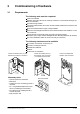
3 Commissioning of hardware 3.1 Requirements The following work must be completed Control unit installed Detection lines, alarm devices etc.
3.2 Installation and connection of hardware CI1145 Full installation details for the various versions of the CI1145 control unit can be found in document e1577! 3.3 Installation of module chassis and internal wiring CS1140 Pos.
3.4 Preparation of the CS1140 electronic modules 3.4.1 Power unit B1F120 Pos.
3.4.2 Pos.
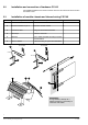
3.4.3 Pos. 1 2 3 4 5 6 7 8 9 Master module E3X101 (supersedes E3X100) Component RAM modules (2x 512kx8) RAM set Z3S070 EPROMs (2x 512kx8) EPROM set CCQ... DIL switch S2 (battery type) DIL switch S3 I-Bus address of ”battery charging unit” DIL switch S4 Service switch Jumper Y8/X8 Contact assignment for ”remote alarm” Jumper X60 Ground short monitoring unit Jumper X30 C-Bus potential Resistors R178/179/196...
3.4.4 Pos. 1 2 Battery charging module E3C011 (supersedes E3C010) Component DIL Switch S2 Battery type DIL switch S3 I-Bus address Preparation Set to battery type used See hardware description (document e1260) Set as per system documentation Default Type «ALARMCOM (FIAM)» address 0 Caution! The jumper between terminals 2 and 3 must always be inserted when the E3C010 is used ( document e1260)! On the E3C011 this connection is already provided on the module. 2 1 3.4.
3.4.6 Pos. 1 2 I-Bus/LON module E3I040 Component DIL switch S3 I-Bus address Resistor R60 LON-Bus termination (EOL) Preparation Set according to system documentation Default address 0 If LON-Bus is not set up as a stub line, R60 must be changed to 50W See also hardware description (document e1260) 100W 2 1 9 Fire & Security Products Siemens Building Technologies Group e1249d 1 01.
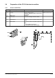
3.4.7 Pos. 1 2 3 4 5 C-Bus gateway E3H020 Component RAM modules (4x 512kx8) or (8x 256kx8) EPROMs (2x 512kx8) EPROM set CKQ... DIL switch S3 C-Bus address DIL switch S5 Select interface path Resistors R...
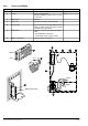
3.4.8 Pos. 1 Line module «MS9i» E3M060 Component DIL switch S3 I-Bus address Preparation Set according to system documentation Default address 0 1 3.4.9 Pos. 1 Line module «Interactive» E3M071 (supersedes E3M070) Component DIL switch S3 I-Bus address Preparation Set according to system documentation Default address 0 Note: Permits connection of up to 128 D-Bus devices but only if all devices used have the designation ”...A” (e.g. DO1151A). Otherwise only 100 devices can be connected.
3.4.10 Pos. 1 2 Line module «Collective» E3M080 Component DIL switch S3 I-Bus address DIL switch S4-2 Line short-circuit evaluation Preparation Set according to system documentation Default address 0 Change to ON if short circuit is to be interpreted as ALARM Set to OFF short-circuit = fault Note: If lines are not yet being used, terminate with corresponding EOL. 1 2 3.4.11 MS5 Adapter E3M220 Pos.
3.4.12 Pos. 1 Line module «AnalogPLUS» E3M111 (supersedes E3M110) Component DIL switch S3 I-Bus address Preparation Set according to system documentation Default address 0 1 3.4.13 Pos. 1 2 Control module «I/O» E3L020 Component DIL switch S3 I-Bus address Maintenance switch S2 Activate test LEDs Preparation Set according to system documentation Default address 0 Set to ON for commissioning Set to OFF 1 Test LEDs 2 13 Fire & Security Products Siemens Building Technologies Group e1249d 1 01.
3.4.14 Pos. 1 2 Control module «Contacts» E3G050 Component DIL switch S3 I-Bus address Maintenance switch S2 Activate test LEDs Preparation Set according to system documentation Default address 0 Set to ON for commissioning Set to OFF 1 Test LEDs 2 3.4.15 Pos. 1 2 3 Control module «monitored» E3G060 Component DIL switch S3 I-Bus address DIL switch S6-1...
3.4.16 Pos.
3.4.18 Pos. 1 2 3 Control module «VdS» E3L030 Component DIL switch S3 I-Bus address Jumper X12 Configure LED4 Resistor R191 (3.
3.4.19 Terminals B3Q460 / 480 / 550 Pos. 1 2 Component Protective cover RAM modules (2x 512kx8) RAM set Z3S070 EPROMs (2x 512kx8) or (2x 1024kx8) for China EPROM set CTQ..., CIQ... or CTQT1.., CIQT1.. for China DIL switch S5 Maintenance switch Jumpers (R49/50/31...
3.4.20 Pos. 1 2 3 Text display terminal B3Q580 Component DIL switch S3 LON-Bus address Resistor R1 LON-Bus termination (EOL) Labels Included in Z5B....
3.4.21 Pos. 1 2 Text control terminal B3Q590 Component DIL switch S3 LON-Bus address Resistor R1 LON-Bus termination (EOL) 3 Labels Included in Z5B....
3.4.22 Pos. 1 Fire department control panel B3Q320 Component DIL switch S3 I-Bus address Preparation Set as per system documentation Default address 0 Afterwards install B3Q320 and connect up databus and supply cables 1 2 3.4.23 Pos.
3.4.24 Pos. 1 2 LON/mimic display converterK3I050 Component DIL switch S3 LON-Bus address Resistor R1 LON-Bus termination (EOL) Preparation Set as per system documentation Default address 0 R1 must be removed if K3I050 is not the last device on the LON-Bus (when wired as a stub line) See also description of hardware (document e1260) 100W Afterwards fit K3I050 and connect data bus, LON-Bus cable, supply cable and the periphery. 1 2 3.4.25 Pos.
3.4.26 Pos. 1 2 3 Printer control K3L080 (for B2Q191) Component DIL switch S1 Baudrate, comm.
3.4.27 PSA interface card K3I090 Pos. 1 Component DIL switch S1 Jumpers X9, X10 X16, X17 X/Y11...15 Resistors R70...R73 2 3 Preparation Set according to application. See table in description of hardware (document e1669) Set according to application. See table in description of hardware (document e1669) Resolder according to application. See table in the description of hardware (document e1669) Default all OFF removed plugged in Y11, X12, X13, Y14, Y15 R70=143W, R71=RW R72=1.5kW, R73=1.
3.5 Install modules CS1140 Procedure Install the module as described in the system documentation I-Bus ribbon cable 1 Plug in (ensure good contact) Supply cable 2 Connect up Plug in battery cables Attach temperature sensor to the battery Electrically isolate controls (e.g. remove relays from base) 3 4 1 I-Bus 2 5/24V supply Note: When switching off for brief periods, remove mains fuse, or remove from power unit and from battery.
3.6 First switch-on Check whether the batteries are connected. Apply supply voltage Observe safety guidelines the CC/CI/CT11 stations load a basic configuration stored in EPROM into the RAM. After approx. 2 minutes this start-up procedure is concluded.
4 Programming the system 4.1 Requirements Control unit is installed and ready for operation Maintenance PC with installed AlgoWorks EP5 is available System-specific data files have been generated (see document e1318): Logic elements are linked with accompanying physical devices Parameters have been set User texts have been defined. Possibly use the SWT11 customer text editor. Locations of the D-Bus devices (automatic detectors, input/output modules, manual call points) are known 4.
4.3 Localization of interactive devices 4.3.
Localize the first device Insert automatic detectors or activate manual call points, input/output modules Wait until the response indicator flashes before the response indicator flashes, no additional devices may be inserted/activated The device must remain inserted for at least 30 seconds ÑÑÑÑÑÑÑÑÑÑÑÑÑÑÑÑÑÑÑÑÑÑÑÑ Ñ ÑÑ ÑÑÑÑÑÑÑÑÑÑÑÑÑÑÑÑÑÑÑÑÑÑÑÑ Ñ ÑÑ ÑÑÑÑÑÑÑÑÑÑÑÑÑÑÑÑÑÑÑÑÑÑÑÑ Ñ ÑÑ ÑÑÑÑÑÑÑÑÑÑÑÑÑÑÑÑÑÑÑÑÑÑÑÑ Ñ ÑÑ ÑÑÑÑÑÑÑÑÑÑÑÑÑÑÑÑÑÑÑÑÑÑÑÑ Ñ ÑÑ ÑÑÑÑÑÑÑÑÑÑÑÑÑÑÑÑÑÑÑÑÑÑÑÑ Ñ ÑÑ ÑÑÑÑÑÑÑÑÑÑÑÑÑÑÑÑÑÑÑÑÑÑÑÑ Ñ ÑÑ ÑÑÑÑ
4.3.
Enter localization index in the commissioning list / ground plan or in the SmartHandy AlgoWorks 00ST0245 09–APR–1997, 14:42 File: C:\AWDATA\DEMO_VPB\DCR001L1.TXT Listing of the logical structure (26447,19533,31046) ––––––––––––––––––––––––––––––––––––––––––––––––––––––––––––––––––––– 001/AR/demo system VPB (1801,1) 001.001/SE fire/2nd floor west (1701,425) 001.001.001/ZO single/1/laboratory 203 (1601,426) 2 >001.001.001.001/001: DOT1151 (1501,427) 3 AI >001.001.001.002/001: DOT1151 (1501,428) 1 >001.001.
4.3.4 Localize with device identification Requirements Automatic detectors: Detector bases installed Detectors not inserted This localization method is possible in a currentless state; the control unit must not, therefore, be installed. It is useful when a detector must be installed in areas which will later become inaccessible.
4.3.5 Localization with the AlgoMan (DZ1154) Instead of entering the ID number and the device type on the commissioning list manually, the DZ1154 can be used to perform this operation electronically. For description of AlgoMan see document x1643 Requirements Automatic detectors: Detector bases mounted Detectors not inserted This localization method is possible in a currentless state; the control unit must not, therefore, be installed.
Deactivate address allocation ( page 93) The data which are now localized in the control unit can be loaded with the function Comm Fast Upload Loc. –> PC in the SWE11 ( Page 94) Load localization data from DZ1154 into AlgoWorks 1. Start up AlgoWorks shell 2. Connect DZ1154 to the maintenance PC 3.
4.4 Localization of AnalogPLUS devices Note: Whenever possible, commissioning should be carried out in the order of installation, especially if the modules DC1135 or DC1136 are used ( see page 58). 4.4.
With the DC1131, the control unit cannot differentiate between the operation of the key for address allocation and any signals at the input. Faults arise in the localization structure if input signals are read in. Recommendation: Extending a system:Carry out ’address allocation by insertion’ (less risk of confusion than with address allocation by activation). New systems: Carry out ’address allocation by activation’ (faster detector response time with localization). 4.4.
ÑÑÑÑÑÑÑÑÑÑÑÑÑÑÑÑÑÑÑÑÑÑÑÑ Ñ Ñ ÑÑÑÑÑÑÑÑÑÑÑÑÑÑÑÑÑÑÑÑÑÑÑÑ Ñ Ñ ÑÑÑÑÑÑÑÑÑÑÑÑÑÑÑÑÑÑÑÑÑÑÑÑ Ñ Ñ ÑÑÑÑÑÑÑÑÑÑÑÑÑÑÑÑÑÑÑÑÑÑÑÑ Ñ Ñ ÑÑÑÑÑÑÑÑÑÑÑÑÑÑÑÑÑÑÑÑÑÑÑÑ Ñ Ñ ÑÑÑÑÑÑÑÑÑÑÑÑÑÑÑÑÑÑÑÑÑÑÑÑ Ñ Ñ ÑÑÑÑÑÑÑÑÑÑÑÑÑÑÑÑÑÑÑÑÑÑÑÑ Ñ Ñ ÑÑÑÑÑÑÑÑÑÑÑÑÑÑÑÑÑÑÑÑÑÑÑÑ Ñ Ñ ÑÑÑÑÑÑÑÑÑÑÑÑÑÑÑÑÑÑÑÑÑÑÑÑ Ñ Ñ ÑÑÑÑÑÑÑÑÑÑÑÑÑÑÑÑÑÑÑÑÑÑÑÑ Ñ Ñ ÑÑÑÑÑÑÑÑÑÑÑÑÑÑÑÑÑÑÑÑÑÑÑÑ Ñ Ñ ÑÑÑÑÑÑÑÑÑÑÑÑÑÑÑÑÑÑÑÑÑÑÑÑ 2nd floor west Office 211 Corridor 200 Office 206 Enter localization index in the commissioning list / ground plan or register in the SmartHandy AlgoWor
4.4.4 Address allocation through activation Requirements Detector bases mounted As a rule, the detectors have already been inserted in the bases when address allocation by activation is started. It is, however, also possible for a detector to be inserted during address allocation and then activated. Fixed devices mounted, electronics inserted During address allocation all devices that have been inserted and installed but not yet localized and allocated in the control unit, must be activated.
Enter localization index in the commissioning list / ground plan or register in the SmartHandy AlgoWorks 00ST0245 09–APR–1997, 14:42 File: C:\AWDATA\DEMO_VPB\DCR001L1.TXT Listing of the logical structure (26447,19533,31046) ––––––––––––––––––––––––––––––––––––––––––––––––––––––––––––––––––––– 001/AR/demo system VPB (1801,1) 001.001/SE fire/2nd floor west (1701,425) 001.001.001/ZO single/1/laboratory 203 (1601,426) 2 >001.001.001.001/001: DOT1131 (1501,427) 3 AI >001.001.001.
The CC/CI11 station and all function units present are automatically localized provided that the bus addresses, models and line numbers (AnalogPLUS line modules only) programmed in the physical structure match the actual settings.
Procedure 1. Using the commissioning list, select the element with the localization index 1 in the logical structure select AlgoWorks 00ST0245 09–APR–1997, 14:42 File: C:\AWDATA\DEMO_VPB\DCR001L1.TXT Listing of the logical structure (26447,19533,31046) ––––––––––––––––––––––––––––––––––––––––––––––––––––––––––––––––––––– 001/AR/demo system VPB (1801,1) 001.001/SE fire/2nd floor west (1701,425) 001.001.001/ZO single/1/laboratory 201 (1601,426) >001.001.001.001/001: DO1151 4 (1501,427) >001.001.001.
Output module DC1154 (if input and output sections are used separately) For details of procedure for manual allocation see page 42 Devices which have more than one D-Bus address, cannot be allocated with the function Auto link. Devices with more than one bus address nevertheless only have one localization index in the localization structure. Such devices must be assigned manually.
’Collective’ input module DC1151 Procedure 1. Switch over from the physical structure to the localization structure Function Loc. Commissioning 2. Using the commissioning list, select a DC1151 input module in the localization structure and the corresponding element in the logical structure Permissible element types: – Collective detector element 1 (’EL col. det. 1’) – Collective detector element 2 (’EL col. det. 2’) – Collective detector element 3 (’EL col. det.
Zone Logical structure ’EL out 2’ Links ’DE DS11i in’ ’DE DS11i out’ Physical structure DC1154 is represented in the physical structure by 2 individual devices (out / in) Function unit Station SWE11: Function unit ’150: DC1154’ SWE11: Localization structure DC1154 is represented in the localization structure by one device 1. Switch over from the physical structure to the localization structure Function Loc. Commissioning 2.
Correct: Incorrect: Zone Logical structure ’EL out 2’ DC1154 No.1 ’EL out 1’ DC1154 No. 2 DC1154 No.
Reference: Localization index of the address allocation or device identification Select DC1154 Select 1st element AlgoWorks 00ST0245 09–APR–1997, 14:42 File: C:\AWDATA\DEMO_VPB\DCR001L1.TXT Listing of the logical structure (26447,19533,31046) ––––––––––––––––––––––––––––––––––––––––––––––––––––––––––––––––––––– 001/AR/demo system VPB (1801,1) 001.001/SE fire/2nd floor west (1701,425) 001.001.001/ZO single/1/laboratory 201 (1601,426) >001.001.001.001/001: DO1151 4 (1501,427) >001.001.001.
Input module (triple) DC1157/DC1157-AA Note: If, after being booted, the system is set in ”Localization” mode, (activation, insertion), the D-Bus addresses for the DC1157 may be redistributed (lower D-Bus addresses). The consequence is that during or after commissioning the DC1157s no longer appear. Action: – Do not boot the system and then switch to ”localization” mode.
Zone Zone Zone e.g. ’EL digital’ DC1157 represented in the physical structure by 3 separate devices (’DE DS11 in’) Logical structure Links Function unit ’104: DC1157’ Physical structure Localization structure DC1157 represented in the localization structure by one device ’FU DS11i’ Station AlgoWorks 00ST0245 09–APR–1997, 14:42 File: C:\AWDATA\DEMO_VPB\DCR001L1.
2. Using the commissioning list, select a DC1192c input module in the localization structure and the corresponding element in the logical structure Permissible element types: – Collective detector element 1 (’EL col. det. 1’) – Collective detector element 2 (’EL col. det. 2’) – Collective detector element 3 (’EL col. det. 3’) – Collective manual call point (’EL DS11c/MS9i man’) Reference: Localization index of the address allocation Device identification 3.
4.5.4 Manual allocation of AnalogPLUS devices (with address allocation) Important Restrictions for the AnalogPLUS System: As soon as at least 1 device has been allocated after uploading, all devices present in the localization structure must also be allocated. On completion of allocation, the configuration must always be downloaded to the control unit.
Input module DC1131/DC1131-AA Procedure 1. Switch over from the physical structure to the localization structure Function Loc. Commissioning 2. Using the commissioning list, select a DC1131 input module in the localization structure and the corresponding element in the logical structure Permissible element types: – ’Digital element’ (’EL digital’) – ’Digital detector element’ (’EL digital det.’) – ’Digital manual call point element’ (’EL digital man.
T-branch module DC1135 (T-tap) Use Single T-branch module for single stub line Multiple T-branch module for two to four stub lines Procedure for localizing a new line 1. Switch over from the physical structure to the localization structure Function Loc. Commissioning 2. The beginning (221: DC1135s or 223: DC1135m) and the end (224: T-T END) of each stub line have the same localization index and remain identified in the physical structure with the prefix * (no counterpart in the logical structure’).
second address, the second detector occupies the third address, etc. At the end of the stub line, after the last detector, T-T END occupies another address. Since the two nodes for the start (DC1135s) and end (T-T END) of the stub line have no counterparts in the logical structure, they remain unlinked (prefix * remains).
Since the eight nodes for the beginning (DC1135m) or the end (T-T END) of the stub line in the logical structure have no counterpart, they remain unlinked! No link with the logical structure! Logical structure DC1135 represented in the physical structure by 8 individual devices (DC1135m / T-T END) four of each Physical structure ’FU DS11a’ Station DC1135 represented in the localization structure by 8 devices all of which have the same localization index Function unit Localization structure Logic
Output module DC1136/DC1136-AA Possible uses The output module DC1136 consists of a digital output section and a digital input section. In the physical structure they are represented as individual devices on an AnalogPlus line (’out’ and ’in’). Normally, this module is operated as output element with confirmation (’EL out 2’). Other links should only be used in exceptional circumstances.
Procedure 1. Switch over from the physical structure to the localization structure Function Loc. Commissioning 2. Using the commissioning list, select the ’DC1136o’ output section from a DC1136 output module in the localization structure and the corresponding ’output element with confirmation’ (’EL out 2’) in the logical structure Reference: Localization index of the address allocation 3. Link nodes together Function Structure Link 4.
Since the input ’225: DC1136i’ is not linked, it appears in the physical structure with the prefix * ( see diagram, page 61). Function unit Localization structure ’226: DC1136o’ ’225: DC1136i’ DC1136 represented in the localization structure by 2 devices DC1136 as input element (output section not used) Use only in exceptional circumstances! Permissible element types: – ’Digital element’ (’EL digital’) – ’Digital detector element’ (’EL digital det.
Input / output module DC1192 Possible Uses The DC1192 input / output module can either be used as an input module for the operation of a collective line (DC1192c) or as an output module for the activation of supervised alarm devices (DC1192h). Procedure when used as an input module 1. Switch over from the physical structure to the localization structure Function Loc. Commissioning 2.
4.6 Address allocation for AnalogPLUS and MS9i devices (according to order of installation) Principle The devices in the physical structure are allocated consecutive D-Bus addresses on the detector bus according to the order of installation. Allocation of addresses can take place at the time of generation of the data file in AlgoWorks. The fire detection system does not have to exist for that purpose. The installation plans for the system act as the reference for the order of installation on the D-Bus.
Special cases Normally, each device occupies one D-Bus address. There are a few exceptions, such as the DC1135 and DC1136 in the AnalogPLUS system, where more than one D-Bus address are required. T-branch module DC1135 The T-branch module can be operated in two different ways. DC1135 with one stub line (zero ohm resistance on the circuit unit removed) A single T-branch module occupies two D-Bus addresses on its own, and each device on the stub line occupies another address.
DC1135 with two to four stub lines (zero ohm resistance on the circuit unit not removed) Regardless of whether the stub lines have devices connected or not, each beginning (DC1135m) and end (T-T END) of the four stub lines always has its own D-Bus address. This means that the multiple T-branch module always occupies eight D-Bus addresses. The eight nodes for the beginning (DC1135m) and end (T-T END) of the stub line have no counterparts in the logical structure and thus remain unlinked.
Output module DC1136 The output module DC1136 consists of a digital output section and a digital input section, each of which occupies its own D-Bus address. The output section always occupies the lower of the two immediately consecutive D-Bus addresses. DC1136 as output element with confirmation Normally, this module is linked with the module with the element type ’output element with confirmation’ (’EL out 2’). Other links should only be used in exceptional circumstances.
DC1136 as input element (output section not used) Use only in exceptional circumstances! Even if only the input section of the module is used, it still occupies two D-Bus addresses. In the physical structure, an output section (DC1136o) and an input section (DC1136i) must be created but only the output section (DC1136o) is linked to the logical structure. The output section always occupies the lower D-Bus address in this case too.
4.7 Address allocation for collective lines Principle Every line of a E3M080 collective function unit is represented in the physical structure as a device ’collective line’ (’DE DS11c line’). Each of these devices is linked to a ’collective detector element 1..3’ (’EL col. det. 1..3’) or a collective manual call point element (EL DS11c/MS9i man). ’AR ’ Area Sections ’SE fire ’ Zones ’ZO single ’ Elements ’EL col det.
4.8 Address allocation for digital inputs-/outputs on function units Principle Every digital input or output on an E3G... / E3L... function unit or on the CPU card is represented in the physical structure by a ’card input’ (’DE card in’) or ’card output’ (’DE card out’) device. All of these devices are allocated to an element. Inputs / outputs on cards need not be localized the location is given by the type of input or output or the terminal.
Procedure 1. Select a ’card input’ (’DE card in’) or ’card output’ (’DE card out’) device in the physical structure and the corresponding element in the logical structure. Reference: Connection diagram Layout/Wiring plan Element/device not yet linked Prefix: * 2. Link nodes together Function structure Link Element and device are shown as linked and localized no prefix 65 Fire & Security Products Siemens Building Technologies Group e1249d 3 01.
4.9 Address allocation for LON-Bus devices Principle The plug-in unit E3I040 is a normal I-Bus station like the plug-in line and control modules. It is represented in the physical structure by the function unit ’FU LON’. As with the D-Bus devices, the LON-Bus devices on the LON-Bus are defined by way of the parameter ’D-Bus address’.
Logical structure No link with the logical structure! Device ’DE LON 2’ Function unit ’FU LON’ Station ’ST CC11’ Physical structure LON-Bus address Mimic display control unit K3R071 / parallel display panel B3R051 The mimic display control unit / parallel display panel is only represented in the physical structure.
4.10 Downloading the configuration data 4.10.1 Principle Each station within the system (CC, CI and CT) has its own configuration file which contains details of the specific system structure. The configuration files must be loaded individually into the various stations. In order to do this, the maintenance PC must be connected to the station concerned. The standard and customer texts are automatically loaded into the stations together with the configuration. If standard texts are altered (e.g.
Principle of customer text download: C-Bus SWE11 CC/CI11 C-Bus 1 CC/CI11 C-Bus 2 Customer text CC/CI11 C-Bus 1 Customer text CC/CI11 C-Bus 2 Download Download Customer text CC/CI11 C-Bus 1 Customer text CC/CI11 C-Bus 2 ÏÏÏÏÏÏÏ ÏÏÏÏÏÏÏ ÏÏÏÏÏÏÏ Customer text CT11 C-Bus 5 Download Parameter ’load texts’ = yes (field 1223, node ST CT11) CT11 C-Bus 5 ÏÏÏÏÏÏÏ ÏÏÏÏÏÏÏ ÏÏÏÏÏÏÏ Customer text CT11 C-Bus 5 Customer text CC/CI11 C-Bus 1 Customer text CC/CI11 C-Bus 2 69 Fire & Security Products Siemens
4.10.
Checking completeness of allocations Before the configuration data is loaded into the CC11/CI11 station, it must be ensured that all of the physical structure devices are linked to a logical element and localized, and that all devices in the localization structure are allocated to an element. During partial commissioning, it can of course happen that elements/devices are present in the configuration but have not yet been localized.
Compatibility of data file and CC/CI/CT program The data file database structure must be totally compatible with the database structure of the station into which it is loaded. AlgoWorks checks that such compatibility exists before downloading takes place. If the versions do not match, AlgoWorks returns an error message and the download operation is not carried out. Description Program name (on EPROM): C C Q 0 0 5.
4.10.3 Control unit CC1142 Procedure Connect the serial interface of the maintenance PC (COM1) and the CC11 control unit (connector ST2 on E3X10x) via the modem box Z3W050/51 + adapter box B3D040 or via the modem box B3D021 Start the SWE11 Load the CC11 control unit configuration data Ensure C-Bus address is correct! Start transfer of configuration data from the SWE11 to the CC11 control unit Function Comm. Fast Download –> CS11 (only with modem box B3D021) or Function Comm.
4.10.4 Control unit CI1142 and terminal CT1142 Procedure Connect the maintenance PC serial interfaces (COM1) to the CI11 main control unit/CT11 terminal (connector ST2 on B3Qxxx) via the modem box Z3W050/51 + adapter box B3D040 or via the modem box B3D021. Start the SWE11 Load configuration data for CI11 control unit/CT11 terminal Ensure C-Bus address is correct! Start transfer of configuration data from the SWE11 Function Comm. Fast Download –> CS11 (only with modem box B3D021) or Function Comm.
4.10.5 Control unit CI1145 Procedure Connect the serial interfaces of the maintenance PC(COM1) and the CI1145 control unit (connector ST6 on E3X120) via the modem box Z3W050/51 + adapter box B3D040 or via the modem box B3D021 Start the SWE11 Load the CI1145 control unit configuration data Ensure C-Bus address is correct (only C-Bus address no.1 is valid)! Start transfer of configuration data from the SWE11 to the CI1145 control unit Function Comm.
5 Exchange of hardware 5.1 CPU cards If a CPU card for a CC1142 (E3X10x), CI1142 (B3Qxxx), CI1145 (E3X120) control unit or a CT1142 (B3Qxxx) terminal is replaced, the following operations must be carried out: Disconnect control unit/terminal from power supply Replace the CPU card, reconnect all cables Re-adjust all switches and jumpers Reconnect power Repeat download of configuration data 5.2 I-Bus cards If an I-Bus card (E3Mxxx, E3Lxxx, E3Gxxx, ...
When replacing manual call points or input / output modules the localization for the replaced devices must be repeated. The following operations must be carried out: Disconnect line from power supply Remove old device Fit new device Reconnect line to power supply In the physical structure, set the D-Bus address of the replaced device to 0 (using Raw Data Editor) Repeat localization and assignment procedure for the device replaced Note: Never set a D-Bus address for the new devices using the AlgoMan! 5.
5.
6 Trouble-shooting 6.1 General trouble 6.1.1 Line cannot be switched to localization Trouble Serious trouble on interactive line Localization cannot be activated 6.1.2 Remedy – At the first commissioning (global device localization, see page 91) the trouble can be identified by means of SWD11 – Load localization data from main control unit to the SWD11, switch to the localization structure, select a function unit and open using the raw node editor – Value of field 1351: gen. FAT.
6.1.
6.1.6 Trouble message in SWE11: ’No data base memory available’ Trouble Not enough available memory on the RAM modules on the main control unit 6.1.7 Remedy – EP5 only supports ”large” RAM modules (Z3S070).
DC1131: – The parameter ’OUT type’ of the output section (device ’DE DS11a out’) is 1 – The parameter ’IN type’ of the input section (device ’DE DS11a in’) is 1 – the values of fields ’OUT type’ and ’IN type’ must be 1 Set values accordingly and once again load the configuration into the CC/CI11 control unit (Comm.
6.1.10 Trouble message on the terminal: ’C-Bus ASIC or RAM’ Trouble Remedy C-Bus ASIC or RAM on the master module (E3X1xx) or the control console (B3Qxxx) faulty. – If the RAM modules are not pushed fully home in the slots, rectify. or – Replace RAM modules or – Replace corresponding module (E3X1xx or B3Qxxx) A new EPROM version has been used (e. g. Upgrade 5.13 → 5.14). Carry out new download! 6.1.
6.2 AnalogPLUS trouble shooting Line short circuit and Line unit in collective mode Line short circuit Loop line Stub line Stub line Hard or soft short–> ”Coll. mode” after 2 minutes unless short is after last device - Hard short or - Soft short 1. At the terminal select poll function unit information and check the number of addresses forwards/ backwards, or connect logger and reconfigure DBus*, Check chain forwards/ backwards 2.
Line break Loop line Stub line Line break or hard short when starting up the line Incorrect line configuration 1. Check event memory to establish whether line short circuit occurred Configure line as stub line (SWE11 –> loop mode 0: no) 2.
Line break AND Line section in collective mode AND Detector Only possible after startup or after reconfiguration of D-Bus with loop line 1. ASIC Startup problem 2. Line break or hard short AND ASIC Startup problem 3. Line break or hard short AND missing devices 4. 2x Line break OR 2x line short OR one line break and one short circuit each Reconfigure D-Bus, wait 2 minutes, repeat if collective mode still active Line break Line break or hard short 1. Check event memory for short circuits 2.
Detector The messages appear when the system is in operation Detector impaired (message) DO/DOT/DT/DC Self-test detects fault 1. Detector has been removed 2. Manual call point defective 3. Detector does not respond Replace devices 1. Insert detectors After commissioning a line 2. Replace manual call points 3. Replace detectors which do not respond Detector impaired (message) AND Terminal configuration (fault) Detectors installed do not match configuration 1. Check detector types 2.
Line unit in collective mode AND Detector (multiple faults) Stub line 1. Detector missing 2. Open line 3. Hard short 4. ASIC Startup problem Reconfigure D-Bus, wait 2 minutes, repeat process if necessary If fault remedied: Startup problem on ASIC - Only possible after startup of a line or after inserting a new device - No Trouble message relating to line short circuit or open line Loop line 1. Number of configured devices does not agree with those installed 2. FET problem 3. creeping line break 1.
Line unit in collective mode AND same number of trouble messages as configured detectors Stub line 1. Milestone missing 2. Open line 3. Hard short 4. ASIC Startup problem Reconfigure D-Bus, wait 2 minutes, repeat procedure if necessary If fault rectified: Startup problem on ASIC 1. At the terminal, select Poll function unit information and check the number of addresses forwards/backwards, or connect logger and reconfigure D-Bus Check chain forwards/backwards. 2.
6.2.1 Signs of a ground short on an AnalogPLUS line The ground short monitor in the E3G070/E3X101/E3X120 signals a ground short (In the event memory, poll earlier ground short messages). During the startup or address configuration the logger identifies unknown devices. Unknown devices which with several logger outputs shift to the line. The logger output shows an incorrect number of devices, in combination with non-recognized devices.
7 Appendix 7.1 Localization mode Notes: All lines with active localization mode are switched off. No fire alarm in an emergency ! When initializing a localization mode in the SWE11 the position of the cursor in the physical structure determines whether the localization mode is activated for all function units, or locally for a single function unit. 7.1.1 Device localization via SWE11 Message: Global device location can only be activated via the SWE11.
Polling localization readiness with SWE11 1. Polling localization readiness Function Comm. Wait until Loc. Ready 2. Wait until readiness for localization in the SWE11 is confirmed. Deactivate device localization: 1. In global localization mode: In the physical structure select any node, but no function unit. 2. In local localization mode: In the physical structure select the function unit in localization mode. 3. End the localization mode via SWE11: Function Comm. Terminate Loc. 7.1.
Deactivating line-by-line device localization: After localization has been completed, localization mode can be deactivated via the terminal as follows: 1. Select Isolation message for the corresponding function unit (line) 2. Press F1 key 3. Enter password requested 4. Select menu point ’End address allocation’ , press ok The line switches back to normal operation and the ISOLATION message disappears. 93 Fire & Security Products Siemens Building Technologies Group e1249d 4 01.
7.2 Upload localization data (CC/CI11 SWE11) Important restrictions for the AnalogPLUS system: As soon as at least 1 device has been allocated after uploading, all devices present in the localization structure must also be allocated. On completion of allocation, the configuration must always be downloaded to the control unit. The localization data are copied when being uploaded from the CC/CI11 control unit into the SWE11. This means that the data remain present in the control unit afterwards.
7.3 Layout of localization structure in the main memory The layout of the localization structure is dependent on whether or not configuration data are already held in the memory of the CC/CI11 control unit. If no data are stored, the control unit generates a localization node for the CC/CI11 station and every existing function unit. As soon as data are present in the memory, the control unit only generates localization nodes for the devices.
7.4 Tips for localization 7.4.1 Commissioning list for address allocation SWE11 printout of the logical structure: AlgoWorks 00ST0251 09–APR–1997, 14:42 File: C:\AWDATA\DEMO_VPB\DCR001L1.TXT Listing of the logical structure (26447,19533,31046) ––––––––––––––––––––––––––––––––––––––––––––––––––––––––––––––––––––– 001/AR/demo system VPB (1801,1) 001.001/SE fire/2nd floor west (1701,425) 001.001.001/ZO single/1/laboratory 201 (1601,426) >001.001.001.001/001: DO1151 (1501,427) 4 5 AI >001.001.001.
7.4.4 SmartHandy for address allocation PSION WorkAbout : The SmartHandy is used for the electronic administration of localization data. The logical structure of a system is loaded by AlgoWorks into the SmartHandy where the localization indexes can be set direct during localization. After being reimported into AlgoWorks, the SmartHandy data are linked to the localization data direct. For the SmartHandy functional characteristics see document e1689.
7.5 Display in SWE11 The status of logical elements, physical devices, and localization structure devices is displayed in the following way in the SWE11: Logical elements or physical devices are NOT linked to a counterpart in the other structure identified by ’*’ I-Bus address Element or device NOT linked Prefix: * CSX no.
Device in the Localization structure is identified with a ’*’, providing it is not localized Next free localization index I-Bus address Device identification Device not localized Prefix: * Device localized no prefix CSX no.
7.
7.7 Activation of interactive and AnalogPLUS devices 7.7.1 Automatic detectors OptoRex PolyRex DZ1193 ThermoRex RE6 Detector exchanger/tester DZ1193 or detector tester RE6 + DZZ1190 Detector tester RE6T WaveRex Sensor B approx. 50mm Response indicator Sensor A Lamp LE3 or Lamp STABEX (in explosion-hazard areas) 7.7.
7.7.3 Input / output modules DC1151 Key for address allocation DC1154 / DC1136 Key for address allocation LED DC1157 / DC1131 Key for address allocation LED DC1134 / DC1135 Key for address allocation LED DC1192 Key for address allocation LED LED 102 Fire & Security Products Siemens Building Technologies Group e1249d 4 01.
7.8 Ground short monitoring The following modules have a ground short monitoring facility: Master module E3X101 (from index b) Master module E3X120 Control module «universal» E3G070 (from index b switchable) Interactive line module E3M071 Within a C-Bus network with electrically connected CC/CI/CT stations (common supply and/or emergency operation connections) the ground short monitoring facility may be active on one module only.
8 Index A Activation of interactive and AnalogPLUS devices, 101 Address allocation for AnalogPLUS and MS9i devices, 58 Address allocation for collective lines, 63 Address allocation for digital inputs-/outputs on function units, 64 Address allocation for LON-Bus devices, 66 Allocations, 38 AnalogPLUS trouble shooting, 84 Auto Link, 33 Automatic allocation of devices using the function ’Auto link’, 39 B B1F120, 5 B2F020, 6 B3Q320, 20 B3Q580, 18 B3Q590, 19 B3Qxxx, 17 B3R051, 20 Battery charging module E3C01
D Data file versions, 72 Device localization line-by-line, 92 Display in SWE11, 98 Downloading customer texts, 68 Downloading the configuration data, 68 E E3C011, 8 E3G050, 14 E3G060, 14 E3G070, 15 E3G091, 15 E3H020, 10 E3I020, 8 E3I040, 9 E3L020, 13 E3L030, 16 E3M060, 11 E3M071, 11 E3M080, 12 E3M110, 13 E3M220, 12 E3X101, 7 Exchange of hardware, 76 F Fire department control panel B3Q320, 20 First switch-on, 25 G Global device localization , 91 Ground plan, 96 Ground short monitoring, 103 I I-Bus/LON-mo
K K3I050, 21 K3I090, 23 K3L080, 22 K3R071, 21 L Layout of localization structure in the main memory, 95 Line cannot be switched to localization, 79 Line module «AnalogPLUS» E3M110, 13 Line module «Collective» E3M080, 12 Line module «Interactive» E3M071, 11 Line module «MS9i» E3M060, 11 Localization following successful download, 95 Localization mode, 91 Localization of AnalogPLUS devices, 34 Localization of interactive devices, 27 Localization with the AlgoMan (DZ1154), 32 M Manual allocation of AnalogPLU
R Remote transmission interface E3G091, 15 Requirements for allocation, 100 RS232 module E3I020, 8 S Safety guidelines, 1 SmartHandy, 97 SWE11: Prefix ’?’ for a node in the localization structure, 80 T Terminals B3Q460 / 480 / 550, 17 Text control terminal B3Q590, 19 Text display terminal B3Q580, 18 Tips for localization, 96 Trouble diagnosis, 79 Trouble message in SWE11: ’communication timeout –> check connections’, 79 Trouble message in SWE11: ’No data base memory available’, 81 Trouble message in SWE11
Siemens Building Technologies AG Alte Landstrasse 411 CH 8708 Männedorf Phone +41 1 − 922 61 11 Fax +41 1 − 922 64 50 www.cerberus.ch 108 Fire & Document Security Products no. e1249d Siemens Building Technologies Group Edition 01.1999 Manual CS11.2 Section 6 Back 01.