Cerberus® CS1140 Fire detection system Commissioning ’Extinguishing’ EP5 Fire & Security Products Siemens Building Technologies Group
Data and design subject to change without notice. / Supply subject to availability. E Copyright by Siemens Building Technologies AG Wir behalten uns alle Rechte an diesem Dokument und an dem in ihm dargestellten Gegenstand vor. Der Empfänger anerkennt diese Rechte und wird dieses Dokument nicht ohne unsere vorgängige schriftliche Ermächtigung ganz oder teilweise Dritten zugänglich machen oder ausserhalb des Zweckes verwenden, zu dem es ihm übergeben worden ist.
1 Procedure . . . . . . . . . . . . . . . . . . . . . . . . . . . . . . . . . . . . . . . . . . . . . . . . . . . . . . . . 1 2 Preparation of hardware . . . . . . . . . . . . . . . . . . . . . . . . . . . . . . . . . . . . . . . . . . . Table 1: Preparation of the E3G080 ’Extinguishing’ control module . . . . . . . . . . . . . Table 2: Preparation of ’Extinguishing’ control panel B3Q440 . . . . . . . . . . . . . . . . . . 2 2 3 3 Measured values and service indicators on E3G080 . . . . . . . . . . . .
II Fire & Security Products Siemens Building Technologies Group 12.
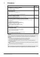
1 Procedure Step Detailed information 1. Preparation of electronic modules Set switches and resistors on E3G080 Set switches on B3Q440 Table 1 Table 2 2. Initial switch-on First set switch ’S1’ on the E3G080 to ON Note: ’S1’ ON = hardware and software blocking of all E3G080 outputs 3. Measure voltage at E3G080 Check voltage of all peripheral equipment connected to the E3G080 Ensure rest potential throughout the area Table 3 4.
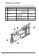
2 Preparation of hardware Table 1: Preparation of the E3G080 ’Extinguishing’ control module No.
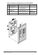
Table 2: Preparation of ’Extinguishing’ control panel B3Q440 No.
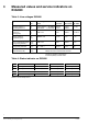
3 Measured values and service indicators on E3G080 Table 3: Line voltages E3G080 Type of line Terminals Line voltage X10-.. ’Rest’ Line voltage Line voltage Line volt’Open line’ ’Short circuit’ age ’active’ Control lines ’Activating element 1’ ’Activating element 2’ 1/2 2/3 without R60/61 80..300mV >880mV with R60/61 0.3...1.6V >1.75V ≤100mV ≤200mV 24...30V Control lines ’Alarm horn’ ’Warning lamp’ 4/5 6/7 2.3V ±10% ≥3,5V ≤350mV 24...
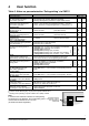
4 User function Table 5: Notes on parameterization ’Extinguishing’ via SWE11 Function Outline description Valve on: confirmation: Line ’Extinguishing activated’ ’Active’ status generates Key stop/block: Function line ’Stop /Blocking key’ ’Active’ status generates Activation time: Duty cycle of activating agent valve (Activating device 2) Flooding time: Flooding time (Duty cycle of activating device 1) Evacuation time: Evacuation time (Delay to activating device 1) Stop –> evacuation time: Function ’St
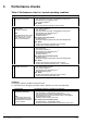
5 Performance checks Table 6: Performance check in ’normal operating condition’ ÑÑÑÑÑÑÑÑÑÑÑÑ ÑÑÑÑÑÑÑÑÑÑÑÑÑÑÑÑÑÑÑÑÑ ÑÑ ÑÑÑÑÑÑÑÑÑÑ ÑÑÑÑÑÑÑÑÑÑÑÑÑÑÑÑÑÑÑÑÑ ÑÑ ÑÑÑÑÑÑÑÑÑÑ ÑÑÑÑÑÑÑÑÑÑÑÑÑÑÑÑÑÑÑÑÑ ÑÑ ÑÑÑÑÑÑÑÑÑÑ ÑÑÑÑÑÑÑÑÑÑÑÑÑÑÑÑÑÑÑÑÑ ÑÑÑÑÑÑÑÑÑÑÑÑÑÑÑÑÑÑÑÑÑÑÑÑÑÑÑÑÑÑÑ ÑÑ ÑÑ ÑÑÑÑÑÑÑÑÑÑ ÑÑÑÑÑÑÑÑÑÑÑÑÑÑÑÑÑÑÑÑÑ ÑÑ ÑÑÑÑÑÑÑÑÑÑ ÑÑÑÑÑÑÑÑÑÑÑÑÑÑÑÑÑÑÑÑÑ ÑÑÑÑÑÑÑÑÑÑÑÑÑÑÑÑÑÑÑÑÑÑÑÑÑÑÑÑÑÑÑÑÑ ÑÑ ÑÑÑÑÑÑÑÑÑÑ ÑÑÑÑÑÑÑÑÑÑÑÑÑÑÑÑÑÑÑÑÑ ÑÑÑÑÑÑÑÑÑÑ ÑÑÑÑÑÑÑÑÑÑÑÑÑÑÑÑÑÑÑÑÑ ÑÑ ÑÑ ÑÑÑÑÑÑÑÑÑÑ ÑÑÑÑÑÑÑÑÑÑÑÑÑÑÑÑÑÑÑÑÑ ÑÑÑÑÑÑÑÑÑÑÑÑÑÑÑÑÑÑÑÑÑÑÑÑÑÑÑÑÑÑÑÑÑ ÑÑ Ñ
Table 7: Individual control functions ÑÑ ÑÑÑÑÑÑÑÑÑÑ ÑÑÑÑÑÑÑÑÑÑÑÑÑÑÑÑÑÑÑÑÑ ÑÑ ÑÑÑÑÑÑÑÑÑÑ ÑÑÑÑÑÑÑÑÑÑÑÑÑÑÑÑÑÑÑÑÑ ÑÑ ÑÑÑÑÑÑÑÑÑÑ ÑÑÑÑÑÑÑÑÑÑÑÑÑÑÑÑÑÑÑÑÑ ÑÑ ÑÑÑÑÑÑÑÑÑÑ ÑÑÑÑÑÑÑÑÑÑÑÑÑÑÑÑÑÑÑÑÑ ÑÑ ÑÑÑÑÑÑÑÑÑÑ ÑÑÑÑÑÑÑÑÑÑÑÑÑÑÑÑÑÑÑÑÑ ÑÑ ÑÑÑÑÑÑÑÑÑÑ ÑÑÑÑÑÑÑÑÑÑÑÑÑÑÑÑÑÑÑÑÑ ÑÑ ÑÑÑÑÑÑÑÑÑÑ ÑÑÑÑÑÑÑÑÑÑÑÑÑÑÑÑÑÑÑÑÑ ÑÑ ÑÑÑÑÑÑÑÑÑÑ ÑÑÑÑÑÑÑÑÑÑÑÑÑÑÑÑÑÑÑÑÑ ÑÑ ÑÑÑÑÑÑÑÑÑÑ ÑÑÑÑÑÑÑÑÑÑÑÑÑÑÑÑÑÑÑÑÑ ÑÑ ÑÑÑÑÑÑÑÑÑÑ ÑÑÑÑÑÑÑÑÑÑÑÑÑÑÑÑÑÑÑÑÑ ÑÑ ÑÑÑÑÑÑÑÑÑÑ ÑÑÑÑÑÑÑÑÑÑÑÑÑÑÑÑÑÑÑÑÑ ÑÑÑÑÑÑÑÑÑÑÑÑÑÑÑÑÑÑÑÑÑ ÑÑ ÑÑÑÑÑÑÑÑÑÑ ÑÑ ÑÑÑÑÑÑÑÑÑÑ ÑÑÑÑÑÑÑÑÑÑÑÑÑÑÑÑÑÑÑÑÑ ÑÑ ÑÑ
6 Overview of operating functions Table 8: Functions ’Extinguishing TEST’ and ’Extinguishing REVISION’ Function Purpose Achieved Blocked Extinguishing REVISION Permits activation of sequence of functions without horn, illuminated warning panel and valves (’active’ status visible at maintenance LEDs E3G080) via AlgoPilot via switch ’S1’ on E3G080 Valves Illuminated warning panel Alarm horn Path ’Extinguishing activated’ via AlgoPilot Valves Permits the disconnection of the path ’E
7 Error diagnosis All faults at the inputs/outputs of the E3G080 are individually displayed at the AlgoPilot. For each of the 4 outputs an LED is provided on the E3G080 for error diagnosis (see Table 4). Separate LEDs are not provided for the inputs, but a special mode enables the identification of each faulty or deactivated input and output. Fault identification at the extinguishing control panel B3Q440 Important: Functions only when a fault is pending Procedure: 1.
Siemens Building Technologies AG Alte Landstrasse 411 CH 8708 Männedorf Phone +41 1 − 922 61 11 Fax +41 1 − 922 64 50 www.cerberus.ch 10 Fire & Document Security Products no. e1456c Siemens Building Technologies Group Edition 12.1997 Manual CS11.2 Section 6 Back 12.