Cerberus® CS1140 Fire detection system Commissioning ’Extinguishing’ EP7F Fire & Security Products Siemens Building Technologies Group
Data and design subject to change without notice. / Supply subject to availability. E Copyright by Siemens Building Technologies AG Wir behalten uns alle Rechte an diesem Dokument und an dem in ihm dargestellten Gegenstand vor. Der Empfänger anerkennt diese Rechte und wird dieses Dokument nicht ohne unsere vorgängige schriftliche Ermächtigung ganz oder teilweise Dritten zugänglich machen oder ausserhalb des Zweckes verwenden, zu dem es ihm übergeben worden ist.
About this document . . . . . . . . . . . . . . . . . . . . . . . . . . . . . . . . . . . . . . . . . . . . . . . . . . . . 1 1 1.1 1.2 Safety regulations . . . . . . . . . . . . . . . . . . . . . . . . . . . . . . . . . . . . . . . . . . . . . . . . Signal words and symbols . . . . . . . . . . . . . . . . . . . . . . . . . . . . . . . . . . . . . . . . . . Safety-relevant working instructions . . . . . . . . . . . . . . . . . . . . . . . . . . . . . . . . . . 3 3 4 8 Procedure . . . . . . . . . . . .
II Fire & Security Products Siemens Building Technologies Group 07.
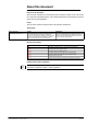
About this document Purpose of the document This document describes the commissioning of the hardware modules of the control units CS1140/45 with extinguishing section. The consistent observance of the instructions ensures a trouble-free and safe application. Scope This document contains information valid for the software variant EP7F.
Disregard of the safety regulations Before they are delivered, the products are tested to ensure they function correctly when used properly. Siemens disclaims all liability for damage or injuries caused by the incorrect application of the instructions or disregard of warnings of danger contained in the documentation.
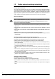
1 Safety regulations This chapter describes the danger levels and the relevant safety regulations applicable for the use of the Cerberus products. Please read the work instructions as well as the chapter ’About this document’ before beginning with the work. 1.1 Signal words and symbols 1.1.1 Signal words and their meaning The danger level − that is, the severety and probability of danger − is indicated by the signal words listed below.
1.2 Safety-relevant working instructions Country-specific standards The products are developed and produced in compliance with the relevant international and European safety standards.
Modifications to the system design and the product Modifications to a system or to individual products may cause faults or malfunctioning. Please request written approval from us and the relevant authorities concerning intended system modifications and system extensions. Modules and spare parts D Locally procured modules and spare parts must comply with the technical specifications laid down by the manufacturer. This compliance is always ensured for original spare parts supplied by us.
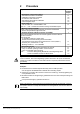
2 Procedure Step Detail information chapter 1. Preparation of electronic modules î Set switch and resistors on E3G080 î Calibration control lines on K5L020 î To shunt line links on E3G110 î Set switches and resistors on B3Q440 î Insert inscription strips 3.1 3.2 3.3 3.4 3.5 2. Initial switch-on î First set switch ’S1’ on the E3G080 to ’ON’ 3.1 Note: ’S1’ −> ’ON’ = hardware and software blocking of all E3G080 outputs 3.
Pos. 3 Preparation of hardware 3.1 Control module ’Extinguishing’ E3G080 Component Preparation Default 1 Programming switch ’S3’: I-Bus address set according to system documentation Address 0 2 Programming switch ’S2’: Determine emer- set according to system documentation gency operation concept S2-1/2 −> ’OFF’ = no function if µP E3G080 malfunctions . see also description in document 1260 all switches to ’ON’ 3 Resistors ’R60/61’ Activating device 1 is between 16 ...
3.3 Pos. Emergency operation link E3G110 Component Preparation 1 Distributor cable: Line links of the extinguishing sections to connect and to shunt according to system documenta- not inserted (contained in module) tion Default 2 Flat cable F12A100/F12A470: Connection to connect according to system documentation line module connector ’ST10’ .
3.5 Pos. 1 Control terminal AlgoPilot B3Q460/48x, B3Q660/68x Component Preparation Default Inscription strips insert −> delivered with strips in ’english’ for AlgoPilot B3Q460/48x, B3Q660/68x, or to be created with Word template (document 006516) B3Q460/48x B3Q660/68x B3Q660/680 1 4 Calibration on E3G080 Each output and each input is controlled and set accordingly.
4.2 Automatic calibration System power up 1. Press ’S4’ key once (service switch ’S1’ must be in position ON) Ü Situation A: When all in−/outputs are in order, or when there is no change to the configuration, or when the monitoring has been deactivated, all LEDs ’H1’...’H4’ are flashing simultaneously during approx. 5 seconds; afterwards the deactivated control lines are briefly displayed in sequence in short time intervals (see table below).
5 User function 5.1 Notes for parameterization ’Extinguishing’ (E3G080) via AlgoWorks Cerberus B3Q440 Fire detector activated Automatic release blocked À Evacuation Autom.+Man.
Deactivating and running mode of warning panel − active until reset −> continuous on − active until reset −> flashing − continuous on until switch off via ’B3Q440’ Ã − flashing until switch off via ’B3Q440’ Ã warning panel activated according to programming 1 9 4 12 Extinguishing agent LOSS − Autom. + manual activation of extinguishing blocked and fault − fault only no extinguishing release extinguishing release possible 0 1 exting.
Cerberus Ê Fire detector activated Ë Evacuation Ì 6 Performance checks 6.1 Performance check in ’Normal operating condition’ Inscription depending on programming B3Q440 Í Automatic release blocked À Î Autom.+Man. release blocked Á Ë Evacuation Extinguishing Ì released Automatic release blocked Extinguishing released Switch off sounder Â Í Fault Switch off warning panel à Πrelease blocked System ON Autom.
3 Activate manually î Alarm organization control unit (î Remote transmission) − LED Ë ’Evacuation’ − Extinguishing horn − Illuminated warning panel − Fire control installations, if existing − Main valve Upon expiry of the evacuation period: î Sector valve Message and LED Ì ’Extinguishing released’ (after acknowledgement) After ’Reset’: î all alarm- and reference messages must be erased possibly fault ’extinguishing NOT ready’ + ’Glass broken’ 4 Activate signal ’Extinguishing activated’ (if existing) î
6.
7 Overview of operating functions 7.1 Functions ’Extinguishing control −> REVISION’ and ’Extinguishing control −> TEST’ Function Purpose Extinguishing control −> REVISION Permits activation of sequence of functions with- î via AlgoPilot ’CT11’ out horn, illuminated warning panel and valves î via switch ’S1’ on E3G080 (’active’ status visible at maintenance LEDs E3G080 see following table chapter 7.1.1) Permits the disconnection of the path ’Extinguishing released’ via AlgoPilot, e.g.
8 Error diagnosis All faults at the inputs/outputs of the E3G080 are individually displayed at the AlgoPilot. For each of the 4 outputs an LED is provided on the E3G080 for error diagnosis (see chapter 4.2). Separate LEDs are not provided for the inputs, but a special mode enables the identification of each faulty or deactivated input and output. 8.1 Fault identification at the operation unit extinguishing B3Q440 NOTE Functions only when a fault is pending Procedure: 1.
8.2 Identification of fault at the E3G080 NOTE Functions only when a fault is pending Procedure: 1. If fault, set switch ’S1’ (E3G080) to ’ON’ 2. Press key ’S4’ (E3G080) once 3. LED H1,H3 and H2,H4 flash in push-pull circuit for approx. 3 sec. 4. Identify the inputs/outputs concerned according to table below 5. Set switch ’S1’ to ’OFF’ H4 H3 H2 H1 ON S1 S4 Note: Each pending fault signal is visible approx. 4 sec.
19 Fire & Security Products Siemens Building Technologies Group Back 07.
Siemens Building Technologies AG Alte Landstrasse 411 CH-8708 Männedorf Phone +41 1 − 922 61 11 Fax +41 1 − 922 64 50 www.cerberus.ch 20 Fire & Document Security Products no. 005109_b_en_-Siemens Building Technologies Group Edition 07.2004 Manual CS11.2 Section 6 Back 07.