Cerberus® CS1140 Fire detection system Planning EP5 Fire & Security Products Siemens Building Technologies Group
Data and design subject to change without notice. / Supply subject to availability. E Copyright by Siemens Building Technologies AG Wir behalten uns alle Rechte an diesem Dokument und an dem in ihm dargestellten Gegenstand vor. Der Empfänger anerkennt diese Rechte und wird dieses Dokument nicht ohne unsere vorgängige schriftliche Ermächtigung ganz oder teilweise Dritten zugänglich machen oder ausserhalb des Zweckes verwenden, zu dem es ihm übergeben worden ist.
1 Main features CS1140 . . . . . . . . . . . . . . . . . . . . . . . . . . . . . . . . . . . . . . . . . . . . . 1 2 Overview technical data CS1140 . . . . . . . . . . . . . . . . . . . . . . . . . . . . . . . . . . . 2 3 Logical and physical structure . . . . . . . . . . . . . . . . . . . . . . . . . . . . . . . . . . . . . 3 4 4.1 Bus systems . . . . . . . . . . . . . . . . . . . . . . . . . . . . . . . . . . . . . . . . . . . . . . . . . . . . . Bus overview . . . . . . . . . . . . . . . . . .
16 Range of cabinets H37... . . . . . . . . . . . . . . . . . . . . . . . . . . . . . . . . . . . . . . . . . . . 43 17 Range of cabinets H38... . . . . . . . . . . . . . . . . . . . . . . . . . . . . . . . . . . . . . . . . . . . 44 18 Range of cabinets H47... . . . . . . . . . . . . . . . . . . . . . . . . . . . . . . . . . . . . . . . . . . . 45 19 Range of cabinets H67... . . . . . . . . . . . . . . . . . . . . . . . . . . . . . . . . . . . . . . . . . . . 46 20 Range of cabinets H98... . .
31.2 31.3 31.4 31.5 Auxiliary power supply . . . . . . . . . . . . . . . . . . . . . . . . . . . . . . . . . . . . . . . . . . . . . . Operation with power supply from control unit . . . . . . . . . . . . . . . . . . . . . . . . . . Operating unit with autonomous power supply . . . . . . . . . . . . . . . . . . . . . . . . . Power supply for remote transmission equipment and accessories . . . . . . . . 78 79 79 80 32 32.1 32.2 32.3 32.4 Emergency power supply . . . . . . . . . . . . . . . . . . . . . .
IV Fire & Security Products Siemens Building Technologies Group 05.
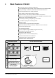
1 Main features CS1140 Fire detection system for modular configuration At least 2000 detectors per CC1143; at least 700 detectors per CI1142 possible For the processing of collective, addressable and interactive detectors Logical and physical structure totally separated Master module as main CPU (for larger systems) Control console as main CPU (for small to medium-size systems) Interfaces for VdS peripheral equipment, printer, PSA/pager, host systems, SPS Different types of input and output modules Autonom
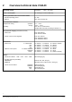
2 Overview technical data CS1140 ±15% Operating voltage 115/230VAC 50...60Hz Power consumption 40...220VA (per converter B2F020) Battery operation in the event of mains failure – standard operating period – optional 12...24h up to 72h (see page 81) Environmental conditions Temperature during operation storage Humidity 0°C ... +40°C –20°C ... +60°C max.
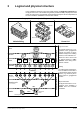
3 Logical and physical structure In the CS1140 fire detection system, the logical structure is completely separated from the physical structure. This enables the greatest possible flexibility. Display and control panel are based on the geographical and organizational aspects and are independent of the actual hardware installation of the detector network.
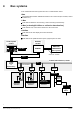
4 Bus systems In the CS1140 fire detection system there are 5 communication levels: I-Bus internal data bus between individual modules in the control unit (line modules, control modules etc.
Fire & Security Products Siemens Building Technologies Group yes Special feature Principle Scanning Network structure – – – Cerberus protocol – Cerberus protocol – collision detection – SPI/Motorola – Manchester coding serial Bus C-Bus cyclic, event controlled event-controlled, presence monitoring master/slave – – – master/master with line separator Short-circuit proof each user connected T-branch Loop line – Number of wires flat cable 26 2 (+3 wires for emergency operation) Number
5 C-Bus stations The C-Bus network contains max. 16 stations (users connected) max. 16 AREAS DMS7000 (managemnt system) CT1142 Gateway C-Bus Nr. 16 C-Bus Nr. 5..16 CERLOOP Control panel CK1142 C-Bus C-Bus network C-Bus Nr. 1..4 Control panel Main CPU I-Bus Line– modules Control– modules CI1142 C-Bus Nr. 1..4 – max. 16 stations – 4 different types of stations – loop line max. 1400m with G51 ø 0.8mm Main CPU I-Bus Line– modules Control– modules CC1142/43 Detector 5.
5.3 Meaning of the suffix 42 or 43 Indicates the outline quantities (RAM size) CI1142 CC1142/43 CT1142 CK1142 5.4 see ’Outline quantities main CPU’ see ’Outline quantities main CPU’ see ’Outline quantities Control terminal’ see ’Outline quantities Gateway’ Chapter 6 Hardware and application limit Type of station Module EPROM-Set Function ’Main CPU’ Function ’Operation’ F CI1142 AlgoPilot B3Q... CIQxxx F CC1142 E3X101 CCQxxx F CC1143 E3X101+K3N010 CCWxxx F CT1142 AlgoPilot B3Q...
5.5 Parallel control panels One parallel control panel can be connected to each AlgoPilot control panel (type ’CT’ or ’CI’) Features the same hardware as AlgoPilot incl.
5.6 Logical AREAS CC CC CI CC C-Bus No. 3 C-Bus No. 4 1 AREA C-Bus No. 2 AREA C-Bus No. 1 2 3 4 5 6 7 8 9 10 11 12 13 AREA 14 15 16 AREA All AREAS control panel within CPU (’CI’ or ’CC’) max. 4 AREAS max.
6 Outline quantities of C–Bus participants This chapter describes the quantitative limits of the C–Bus participants. Possibly performance related limitations depending on the outline quantities are not taken into account. For earlier EPs consult the corresponding release notes or the corresponding edition of this document, but use chapter 6.1.4, ’Maximum number of criteria in zone control 4 and 6 (RAM)’ of this document. 6.
6.1.1 Maximum number of devices (RAM) per station select station with higher RAM capacity or an additional station no number of devices
6.1.2 Limits in the logical structure The limits in the logical structure are given by the node–type, by the highest possible CSX number and the maximum amount of display–digits. These limits are given by the system and are independent of the memory capacity.
Example: CI1142 with 150 control zones with an average of 9 control criteria. The point of intersection for the number of control zones (150) and the number of criteria per control zone (9) must be within the permitted range. Diagram ’Maximum ratings of controls’ CI1142 and CC1142 Number of criteria per control zone 16 criteria per control zone = max. 150 control zones 16 14 12 10 example 9 4 criteria (average) per control zone = max.
6.1.5 Maximum number of I–Bus–modules ÁÁÁÁÁÁÁ ÁÁÁÁÁÁÁ ÁÁÁÁÁÁÁ ÁÁÁÁÁÁÁ ÁÁÁÁÁÁÁ ÁÁÁÁÁÁÁ ÁÁÁÁÁÁÁ ÁÁÁÁÁÁÁ ÁÁÁÁÁÁÁ ÁÁÁÁÁÁÁ ÁÁÁÁÁÁÁ ÁÁÁÁÁÁÁ Table ’Maximum number of I–Bus–modules’ select station with higher capacity or use an additional station Type of station I-Bus-modules number of I-Bus-modules
6.2 Control terminal limits (CT) define the required number of control terminals by going through this flow chart 6.2.1 Maximum number of texts The total number of texts that can be displayed on one control terminal is limited.
6.3 Gateway limits (CK) check gateway configuration 6.3.1 Limits of the memory (RAM) CK1142 for C-Bus network max. 4 stations CC1142/43, CI1142 EPROM set ’CKQxxx’ RAM set ’Z3S070’ (2 sets required) For the above configuration there are no memory limits existing for ≤ EP5 (SR1). the configuration of the gateway is checked The given limits for the station (CI/CC), the control terminal (CT) and the AW–Shell tools have to be checked as well! 6.4 AW–Shell tools limits 6.4.
6.4.2 Limit of ’Compare data files’ / ’Compare base data variants’ (SiteDiff) There are 3 different limitations for the function ’Compare’: – The total of customer texts (once the amount of ZONE entries, and two times the amount of SECTION entries and 100 station texts) must not exceed 4000 (.....t.dat).
7 Specify hardware required In order to be able to specify the hardware required, system key data must be specified according the following procedure: 1. Specify number and type of detection lines dependent on: Detector series Number of detectors, input and output modules Building structure 2.
8 Choice of appropriate control unit cabinet For a suitable normal application, the required control unit cabinet can be worked out from the outline quantities for the main CPU.
9 CI1142 in cabinet H38... (flat) Component of Z3I470 H38G220: Set with – cabinet – door – module chassis – earth terminals * incl.
CT1142 (additional operating facilities) for details see page 36 C-Bus E3C011 B2F020 24V 24V Akkus AX12.. 24V 5V E3M... E3G070 RS232 or K3I090 2 E3G... E3L... E3I040 1........7 1..2 24V 1 CI1142 I-Bus AlgoPilot AlgoPilot CT111B3Q...
10 CI1142 in cabinet H38... (deep) Component of Z3I470 H38G320: Set with – cabinet – door – module chassis – mains terminals * incl.
CT1142 (additional operating facilities) for details see page 36 C-Bus Mains B2F020 24V 24V 5V E3C011 24V RT = Remote transmission Akkus AX12.. CI1142 I-Bus AlgoPilot B3Q... AlgoPilot CT111 E3G070 E3I020 RS232 1 1..2 or K3I090 24V B3R051 2 B3Q320 E3G... E3L... E3M... E3L030 1........
11 CI1142 in cabinet H47...
CT1142 (additional operating facilities) for details see page 36 C-Bus Mains B2F020 24V 24V 5V E3C011 24V Akkus AX12.. CI1142 I-Bus AlgoPilot B3Q... AlgoPilot CT111 E3G070 E3I020 RS232 1 Basic equipment Option RT = Remote transmission 1..2 or K3I090 24V B3R051 2 B3Q320 1........7 Z3B171 Fire control installation E3I040 LON-Bus RT 250VAC 10A for details see page 38 Printer internal or –> see page 71 Pager external printer –> see page 75 E3G... E3L... E3M...
12 CC1142/43 in cabinet H47... Module chassis H47...
CT1142 (operation = separate C-Bus station) for details see page 36 Basic equipment C-Bus Mains Batteries AX12.. K3N010 24V CPU 24V Battery charging mdule I-Bus Driver E3I020 1..........8 24V or RS232 1 Z3B171 RT CC1142/43 B2F020 E3X101 1..2 Option RT = Remote transmission K3I090 E3G... E3L... E3M...
Auxiliary power supply in second H47 housing ÒÒÒÒÒÒÒÒÒ ÒÒÒÒÒÒÒÒÒ ÒÒÒ ÒÒÒ ÒÒÒ ÒÒÒ ÒÒÒ ÒÒÒ ÒÒÒ ÒÒÒ ÒÒÒ ÒÒÒ ÒÒÒ ÒÒÒ ÒÒÒÒÒÒÒÒÒ ÒÒÒÒ ÒÒÒ ÒÒÒ ÒÒÒ ÒÒÒÒ ÒÒÒÒ B2F020 21 Cable duct 34 35 36 44 E3H020 + 2x Z1I030 43 45 52 max. 8 37 Mains terminals Z3I450 47 48 Housing set H47G611 or H47E100 and H47T111 for details see page 45 E3... Z1I... E3... Z1I...
12.2 Cable sets for supplementary power supply in H47 housing The Z3I870 cable set can always be used for the wiring of the supplementary power supply. The cable set contains all the necessary cable and wires for connections to the next extension. CC1142/43 for H47E100 and H47E110 Z3I350 Z3I870 1st. extension Z3I870 2nd. extension Z3I870 3rd. extension for wiring details ³ see document e1260 29 Fire & Security Products Siemens Building Technologies Group e1076g−12 05.
13 CC1142/43 in cabinet H67... H67G601/611: Set with Z1I070 or Z1I040 or Z1I050 – door – frame – module chassis – terminal blocks – mains terminals – battery supporting plate – relay rail can be plugged intoconnection block Connection panel max.
CT1142 (operation = separate C-Bus station) for details see page 36 Basic equipment C-Bus Mains Batteries AX12.. K3N010 24V CPU 24V Battery charging mdule I-Bus Driver E3I020 1..........8 24V or RS232 1 Z3B171 RT CC1142/43 B2F020 E3X101 1..2 Option RT = Remote transmission K3I090 E3G... E3L... E3M...
13.1 Installation possibilities on module chassis H67... Special feature: H67E100 has 3 different hole patterns for mounting. As a result, the relationship between connection block / modules / batteries can also be arranged differently Grid for modules Mounting variants AX1201 or AX1209 04Mains Connection panel max.
13.3 Combination possibilities H47 + H67 cabinet or H98 cabinet Details on module chassis: H67E101 see page 46 H47E100 see page 45 Profil rail on rear panel of H98G600 32 module spaces 3 battery sets 32 module spaces 5 universal brackets Note: The following modules can not be mounted on G1E010: – Z1I020....
13.
13.5 Cable sets for supplementary power supply The Z3I870 cable set can always be used for the supplementary power supply wiring. The cable set contains all the necessary cable and wires for connection to the next extension. CC1142/43 for H67E101 and H47E110 Z3I350 Z3I870 1st. extension Z3I870 2nd. extension Z3I870 3rd. extension Z3I870 4th. extension for wiring details ³ see document e1260 35 Fire & Security Products Siemens Building Technologies Group e1076g−13 05.
14 Control consoles AlgoPilot B3Q... 240 x 64 dots illumination red/yellow illumination red/yellow B3Q460 (Standard) B3Q480 (Nordic) B3Q485 (CH) 240 x 128 dots 240 x 128 dots 240 x 64 dots illumination red/yellow B3Q550 (Wagner) 14.
RS232 module E3I020 is mounted at the rear of the control console by means of accessories Z1B020. For the pager interface K3I090 see page 76 for details E3I020 see document d1393 for details K3I090 see document d1669 Supplied with Z1B020: Plug-in terminal 12 cont.
14.2 Installation possibilities Built into H23/H26 cabinets Built into H47/H67 cabinets Dimensions: see page 26 + 30 Dimensions: (H23) W = 125 H = 219 D = 76 (H26) W = 366 H = 219 D = 76 AlgoPilot B3Q... B3R051 by choice B3Q320 B3R051 H23B010 H23B040 AlgoPilot B3Q... for recessed mounting see page 42 Built into H28 cabinet Dimensions: W = 520 H = 300 D = 70 Built into H37 cabinet AlgoPilot B3Q... by choice B3Q320 B3R051 H23B020 H23B040 Dimensions: W = 510 H = 540 D = 200 AlgoPilot B3Q...
Basic equipment Option CC1142/43, CI1142, CK1142 CT1142 Mains C-Bus B2F020 E3C011 separately connected parallel indicator activation of Mimic Display see page 60 B3Q320 Batteries AX12.. Parallel branching permissible I-Bus 24V supply line E3I020 or RS232 K3I090 1 Data bus F12A100 2 max. 1000m B3R051 B3R051 F12A100 internal or external printer Pager –> see page 76 Printer –> see page 71 B3R051 B3R051 F12A100/470 B3R051: – can be installed separately, however at max. 1000m – max.
14.3 Connection lines between control unit and external operating units Options: B3Q320 (Fire department control panel) Control panel AlgoPilot B3Q... Control panel AlgoPilot B3Q... B3R051 (Parallel indicators) Printer, paging system/pager Loop C-Bus max. 1000m per Loop with ø 0.6mm (incl. return line) max. 1800m per Loop with ø 0.8mm (incl. return line) 2..
15 Range of cabinets H23... / H26... / H28... for operating units B3Q... / B3R051 / cover plate H23B020 with lock (DOM) Front can not be pivoted for parallel indicator panels (4x B3R051), with lock (DOM) H23G230: Dimensions 125 x 219 x 76mm Material plastic Colour Pantone 421 grey Protection category IP40 for printer B2Q191with lock (DOM) H26G220: Dimensions 366 x 219 x 76mm Material plastic Colour Pantone 421 grey Protection category IP40 H28...
15.
16 Range of cabinets H37... H37G410: H37G420: Dimensions 540 x 510 x 200mm Material steel sheet Colour RAL7035 light grey Protection category IP30 Dimensions 540 x 510 x 214mm Material steel sheet Colour RAL7035 light grey Protection category IP30 H37G430: Dimensions 540 x 510 x 200mm Material steel sheet Colour RAL7035 light grey Protection category IP30 H37T000 H37Z010 for AlgoPilot B3Q...
17 Range of cabinets H38... Doors can be closed with 2 Allen screws H38G210/220/230: Dimensions 520 x 602 x 100mm Material steel sheet Colour RAL7035 light grey Protection category IP50 H38G310/320: Dimensions 520 x 602 x 155mm Material steel sheet Colour RAL7035 light greyProtection category IP50 for AlgoPilot B3Q... for H23B010 or H23B040 see page 20 for B3Q320 / B3R051/H23B010 or H23B040 see page 22 and 38 for details of the cabinets H38...
18 Range of cabinets H47... Doors can be closed with DOM lock Including module chassis with: – Cable ducts – 3 terminal blocks Z3I330 – Relay bar (max. 8x Z3B171) – Mains terminals (pre-wired) – Battery support plate for AlgoPilot B3Q... for B3Q320 / B3R051 / H23B010 or H23B040 see page 20, 26 and 38 H47G601/611: Dimensions 434 x 735 x 300mm Material steel sheet Colour RAL7035 light grey Protection category IP30 for details of the cabinets H47...
19 Range of cabinets H67... Doors can be closed with DOM lock Module chassis included, with: – cable ducts – mains terminals (pre-wired) – battery support plate H67T101/H67T111: Dimensions 434 x 110 x 300mm Material steel sheet Colour RAL7035 light grey Protection category IP30 for AlgoPilot B3Q... for B3Q320 / B3R051 / H23B010 or H23B040 see page 20, 26 and 38 for details of the cabinets H67...
20 Range of cabinets H98... for details see document x654 / ZH4.2 Installation of the module chassis H47E.../H67E...
21 Overview 19” accessories Application of non–Cerberus cabinets Modules 19” accessories Z3B180 476207 Z2G030 378198 G2A130 475088 G2A140 484228 G2F031 409290 19” adapter set for H47E.../H67E... Hinge 19”/6HE Adapter plate 19”/6HE Adapter plate 19”/6HE Front frame 19”/6HE consisting of hinge and spacer profile for AlgoPilot B3Q... for B3R051 / B3Q320 etc. for printer B2Q191 48 Fire & Security Products Siemens Building Technologies Group e1076g−21 05.
22 Principle of internal pre-wiring Module chassis H47E... Module chassis H67E... Connection cable Z1I030 short 0.5m 19 cond. Connection cable Z1I050 long 0.8m 19 cond. Connection cable Z1I020 short 0.5m 9 cond. Z1I060 short 0.5m 4 cond. Terminal block Z1IK020 for direct connection to periphery Connection cable Z1I040 long 0.8m 9 cond. Z1I070 long 0.8m 4 cond.
23 Line modules There are different line modules for the various detection systems: E3M071 interactive detectors E3M171 interactive ’Ex’ detectors E3M120 CBA8000/TS9000 detectors E3M111 AnalogPLUS detectors E3M060 MS9i detectors E3M080 collective detectors (limit value detectors) I-Bus E3X101 ST10 ST10 E3M120 1........4 max. 500mA ST10 = connector for special application (E3G110) see page 69 24V ST10 E3M080 1 2....6 24V max. 500mA 24V ST10 E3M060 E3M111 7 8 E3M220 24V MS5 E3M171 max.
23.
23.2 Detection line ”interactive” Number of addresses: max. 128, restrictions for certain types of devices 1) T branches possible everywhere max. 5 detectors MS716 collective MS9 collective DS11 collective D2401 Stub line max. 32 detectors T branch 1 Loop line DO115x DOT115x E3M071 DT115x ÖÖÖ ÖÖÖ DC1157 DC1151 DO115x DOT115x DM115x 3 contacts DOT115x D-Bus max.
23.3 Detection line ”interactive” Ex Number of addresses: max. 32, restrictions for certain types of devices 1) T branches allowed 1 Stub line the software can not proof wheter or not Non–Ex–detectors are in the explosion hazard area non–Explosion hazard area Explosion hazard area D-Bus max. 32 addresses / 70Ω 1) E3M171 SB3 Dxx115x DM115x–Ex DOT1151A–Ex DT1151A–Ex DF1151-Ex Dxx115x DT1151A–Ex Dxx115x DOT1151A–Ex 1) for details see documents e1508 and e1204 23.
23.5 Detection line ”AnalogPLUS” Number of addresses per line: max. 128, restrictions see 1) All detectors, manual call points and input/output modules with integrated line separator T branches via module DC1135 DJ1192 DJ1191 4 Loop lines DF1191/92 1 DC1131 DO113x DM113x DT/DOT/DO113x DOT113x AnalogPLUS-Bus max.
23.6 Detection line ”MS9i addressing” The E3M060 enables the integration of existing parts of a system with series MS9i/MS7i detectors Number of elements (addresses) per line: max. 50, but this depends on type of element 1) Parallel detectors (slaves) Z9..Si max. 4 detectors 1 Loop line ÖÖ ÖÖ ÖÖ ÖÖ Z9..Mi F910 R936 R970 E3M060 MS716i MS9 MS716 collective MS9 collective DS11 collective D2401 K5M010 F930 R930 24VDC AT50Mi Addressing bus MS9i max.
23.7 Detection line ”collective” All detectors on a line have the same collective address (ZONE) Line termination depending on application by means of transzorb or EOL22 (Ex) Number of detectors per line: DS11 detectors: max.
24 Control modules Application of control modules Activation of fire control installations (shutting-down ventilation, closing fire dampers etc.
24.2 Control outputs station type CC1142/43 Basic equipment Additional control modules according to application I-Bus CPU E3X101 E3L020 Driver Driver 1..........8 24V 1..........16 1..........8 1..........6 30VDC 1A 250VAC 10A 250VAC 10A max. 24V/2A (max. 4A/E3G060) Fire controlinstallations 24.3 E3G060 Driver Z3B171 Z3B171 RT E3G050 Control outputs station type CI1142 Basic equipment Additional control module according to application I-Bus B3Q... CPU E3L020 Driver E3G070 Driver 1.....
24.4 CPU-overlapping controls all-AREA single-AREA CT CT CK gateway C-Bus CC/CI CC/CI CPU 1 A1 CPU 2 A2 A3 A4 A5 CC/CI CPU 3 A6 A7 A8 A9 CC/CI CPU 4 A10 A11 A12 A13 A14 A15 A16 = AREA initiating data point control ZONE/ELEMENT must be within the same CPU control device Limitation: see chapter 6.1.4 59 Fire & Security Products Siemens Building Technologies Group e1076g−24 05.
Mimic Display panel outputs station type CT1142 and CI1142 24V F12A100 or F12A470 AlgoPilot B3Q... K3R072 24.5 1 LED flat cable F50F410 cable length 1m, 24 red LEDs 48 LED flat cable F50F410 Mimic Display panel Parallel branching permissible Z3I530 AlgoPilot B3Q... (Adapter) Data bus max.
24.6 Relay outputs station type CT1142 and CI1142 Flat cable supplied with K3G060 F12A100 or F12A470 AlgoPilot B3Q... K3G060 K3G060 1 24V 48 K3R072 max. 24 units, however max. 8 addresses 1 24 outputs max. 30V/1A 24 1 24 outputs max. 30V/1A 24 for details see document e1260 Parallel branching permissible Z3I530 (Adapter) Data bus max.1000m (not monitored) 48 K3R072 max. 24 units, however max. 8 addresses K3G060 K3G060 1 24V AlgoPilot B3Q...
25 Floor indicator panel 25.1 Features Activation via local communication Bus ’LON’ 3 different types of device available B3Q580 = Text display terminal B3Q590/595 = Text control terminal K3I050 = LON/Mimic Display converter Connection via I-Bus/LON module E3I040 (I-Bus-module) the function ’LON-Bus’ is possible once per station type ’CI’ and ’CC’ max.
25.2 LON/Mimic Display p.c.b K3I050 Dimensions: 106 x 200 x 14mm G allows connection of Mimic Display p.c.bs K3R072 or parallel indicator units B3R051 H23G230 to K3R072/B3R051 K3I050 (max.24 units, however max. 8 addresses) G various local inputs/outputs Z3I530 Input key ’buzzer switch-off’ Lon-Bus 24V The functions of the in-/outputs refer on the K3R072 resp. B3R051 Input key ’lamp test’ Output local buzzer 50cm Z3I520 Output LED ’operation’ 25.
26 Gateway 26.1 Main features Connection C-Bus network DMS / LMS via V28 interface (RS232) Conversion of C-Bus CERLOOP/CERBAN For bridging distances of up to 1000m (double V28 modem integrated) For distances >1000m use FSK/PSK modem Max.
26.
27 Remote transmission Most fire detection systems are linked to a remote transmission system. Therefore in case of alarm (alarm stage 2) the fire detection system must initiate the remote transmission device (RT-device).
27.1 CPU-overlapping remote transmission all-AREA single-AREA CT CT gateway CK C-Bus CC/CI CPU Area 1 Area 2 CC/CI CPU Area 3 CC/CI CPU Area 4 common RT–device for all AREAS within CPU common RT-device for several CPUs initiating data point control ELEMENT ’RT’ RT-device – also functions via emergency operation circuit 67 Fire & Security Products Siemens Building Technologies Group e1076g−27 05.
28 Extinguishing 28.1 Main features extinguishing SECTION Extinguishing section consists of: Control module E3G080 (I-Bus module) Operating unit B3Q440 ’Extinguishing’ option: monitoring card K5L020 for monitoring and control of additional magnetic ext. valves E3G080 is designed for one extinguishing SECTION max. 600m 5 wires ø 0.8mm Line and device monitored Z1I030/050 E3G080 Z1K030 CT1142 K5L020 details see document e1260 C-Bus CC1142/43 CI1142 I-Bus I-Bus E3X101 E3M...
28.2 Option emergency operation link E3G110 Enables automatic activation of extinguishing through interlinked areas even if the main CPU malfunctions. The detectors in the extinguishing SECTION must be distributed over 2 independent detection lines. CC1142/43, CI1142 CPU E3X101 or B3Q... I-Bus E3G080 K1 E3G110 K1 K1 ST1 E3M071 ST8 ST10 K1 E3M071 ST10 K1 1......
28.
29 Printer interface 29.
29.3 Application variant CC11 to printer CC1142/43 I-Bus E3X101 ST2 F20A020 ST1 E3I020 X2 RS232 C-Bus Z1I030/050 E3I020 max.1000m or K3 B2Q191 24VDC (9...36VDC) K2 F20A020 CC1142/43 I-Bus E3X101 ST2 (TTL) F20A410 A3 B2Q191 max. 1m 24VDC C-Bus K2 F20A410 Requirement: The printer B2Q191 must be in the same cabinet as the main CPU (E3X101) or in an immediately adjacent cabinet.
29.4 Application variant CI11 CI1142 AlgoPilot B3Q... E3I020 F20A140 Z1K030 I-Bus ST2 F20A140 to printer ST1 E3I020 X2 RS232 C-Bus max.1000m or K3 B2Q191 in cabinet H38 24VDC (9...36VDC) K2 to printer AlgoPilot B3Q... F20A140 CI1142 I-Bus ST2 F20A140 ST1 E3I020 X2 RS232 C-Bus max.1000m or K3 B2Q191 24VDC (9...36VDC) K2 Z1I030 E3I020 in cabinet H47 Modules B2Q191 E3I020 Z1K030 Z1I030 Z1I050 F20A140 484888 460239 484231 475509 475525 496863 Logging printer 9...
29.
30 Paging interface 30.1 Features The paging interface card K3I090 is a universal module, and is used to analyse the data sent from a control unit to its printer output and transmit these data in ESPA 4.4.4 format to the paging system. Details see document e1669 Can be used in the following system configurations: Control unit CC1142/43 or CI1142 AlgoPilot B3Q... CT1142 other System (any other system that uses an RS232 printer output to display its system messages.) 30.
30.3 Application variant CT11 use ribbon cable F20A020 ITF Box B3D021 for download to paging system to PC (Tool) to external printer use ribbon cable F20A410 to internal printer slide the interface in from the right side, and attach it with the two supplied screws. ground via mounting screws remove the two pan-head screws from the AlgoPilot cover and attach the shielding box with those two and the two supplied screws. supply plug delivered with mounting set Z1B060 CT11 K3 1 AlgoPilot B3Q...
31 Power supply Concept The power supply for the CS1140 fire detection system consists of: Converter (mains voltage system voltage 29,6V) Battery charging unit (integrated in E3X101 or by means of E3C011) Batteries (lead) (capacity as required) Special functions automatic battery load test Battery charging characteristic can be programmed according to make Application Determine required battery capacity individually see page 81 Protection of mains lead only in special cases see page 85 max.
31.2 Auxiliary power supply Auxiliary batteries for the basic power supply: max. 1x E3C011 with battery set as an addition CT1142 Additional batteries with auxiliary power supply: max. 3 battery sets per B2F020 possible Mains Mains Basic emergency power supply 1st extension 1 C-Bus TF* 2 Batteries AX12.. B2F020 TF* 3rd extension 3 Batteries AX12.. B2F020 TF* E3C011 Battery charging unit 24V 2nd extension Batteries AX12.. E3C011 4th extension 4 TF* Batteries AX12..
31.3 Operation with power supply from control unit from CC1142/43 operating unit is connected to E3X101 from CI1142 operating unit is connected to AlgoPilot B3Q... Output 1 CT1142 CT1142 + / – / Earth + / – /Earth Output 2 CC1142/43 Output 1 24V / 2A CI1142 Output 2 24V / 2A E3X101 AlgoPilot B3Q... I-Bus I-Bus Note: A 2nd supply output is only necessary for operating units which must comply with EN54 (at least 1 operating unit per system) 31.
31.5 Power supply for remote transmission equipment and accessories with CC1142/43 with CI1142 Equipment is connected to E3X101 Equipment is connected to E3G070 CI1142 CC1142/43 E3X101 I-Bus Res: 24V / 2A AlgoPilot B3Q... I-Bus E3G070 RT: 24V / 2A 0.63A 24V / 0,63A Cable set Z3I390 required for RT: Cable set Z3I390 required RT other equipment (e.g. printer) RT = Remote transmission Remote transmission or other equipment (e.g.
32 Emergency power supply 32.1 Specifying battery capacity Battery rated capacity The battery rated capacity is based on the discharge over a period of 20 hours Faster discharge causes a loss of capacity: discharge over 12-hour period: 9% loss (K = 1.1) Ageing of battery With increasing age, the battery suffers a loss of capacity Allow a safety factor for ageing (Total quiescent current × 1.25 or battery capacity × 0.
32.3 Quiescent current table quiescent current when on battery operation (24V) as basis for individual calculation of emergency power supply the current for the 5V supply is included in these values Module B2F020 B1F120 B2Q191/B1Q101 B3Q320 B3Q440 B3Q460/480/485/ 490/550 B3Q560/600 B3Q580 B3Q590/95 B3R051 E3C011 E3G050 Quiescent current at 24VDC (typical) 0 0 33mA 17mA 25mA max.
33 Alarm concept The alarm concept must be worked out individually for each system The important thing is to pass on the alarm message quickly to the appropriate group of recipients The requirements vary between «Discreet alerting» of the reconnaissance squad, e.g. via staff paging system «Alarm / evacuation» for people familiar with the location «Alarm / evacuation» for people unfamiliar with the location «Area evacuation», e.g. building storey 33.
Determine the alarm organization the CS1140 fire detection system CS1140 has up to 16 programmable organization levels (AREAS) a number of ”Alarm variants” are possible (can be selected per ZONE) the time countdown memories ”V1” and ”V2” must be specified individually the time countdown memory ”V2” can be defined per ZONE (if required) various special local functions are provided the alarm organization is programmed individually (via maintenance PC) Organization of system operation The place of operation o
34 Protection elements Purpose For protection against voltage surge and electromagnetic influence (EMI). Normal field of application Control unit No additional protection measures required. All modules have integrated protection against voltage surge and electromagnetic influence, however no lightning protection. Installation In general use twisted cable, for detection lines, data lines, external supply lines and lines to alarm devices.
35 Commissioning for details see document e1249 The CS1140 fire detection system is designed for rational systems engineering. Connection work at the control unit can be done by non specialist personnel (e.g. outside electricians). However, co-ordinated supervision is still essential. Specially trained personnel with a maintenance PC are required for commissioning (service engineer).
36 Parameterization for details see document e1318 Parameters are set for the CS1140 fire detection system via the maintenance PC by means of the Cerberus software tool set ”AlgoWorks” (module ”SWE11”) Online-Help text in various languages 2 user levels (service engineer; Person locally responsible) AlgoPilot B3Q... CPU / Operating unit download system data ST2 Modem box RS232 B3D021 CC1142/43 C-Bus Maintenance PC ST2 I-Bus CPU E3X101 E3M...
37 CS1140 modules in alphabetical order A AX1201 AX1209 AX1210 AX1212 225487 462936 475570 484325 Battery Battery Battery Battery 12V/27Ah 12V/42Ah 12V/15Ah 12V/12Ah 495233 504580 470588 484888 505259 392653 460213 475952 546551 546577 546580 546593 546603 546616 496177 496180 534110 546629 490513 Converter 115/230VAC>24VDC 3A Logging printer19”/3HU, 24VDC Converter 115/230VAC>29.
F F12A100 F12A470 F14A230 F14A320 F14E320 F20A020 F20A140 F20A410 F50F410 495275 495288 402967 319652 451439 476317 496863 495327 529141 Flat cable micro 12 cond., 0.4m Flat cable micro 12 cond., 1.5m Flat cable 14 cond., 0.25m Flat cable 14 cond., 0.5m Y flat cable 14-wire, 0.5m Flat cable micro 20 cond., 0.165m Flat cable micro 20 cond., 0.650m Flat cable micro 20 cond., 1m LED flat cable for K3R072 384276 475088 484228 409290 Universal bracket 3HU Adapter plate 19”/6HU for AlgoPilot B3Q...
K K1D012 K1D081 K1D121 K1D140 K1H021 K3I050 K3I090 K3G060 K3N010 K3R072 K5L020 463760 463773 470601 470614 452234 496766 510820 528786 522818 528605 441232 Modem p.c.b. V28 Dual modem p.c.b. V28 Dual modem p.c.b. FSK/PSK Modem p.c.b. FSK/PSK Communication p.c.b. LON/Mimic Display converter Pager interface Relay card RAM extension card 1024Kx8Bit for CC1143 Mimic Display activation.. Dual sector extinguishing p.c.b.
Z5B440 Z5B450 Z5B460 Z5B470 Z5B480 Z5B490 Z5B500 Z5B510 Z5B520 Z5B530 Z5B540 Z5B550 Z5B560 Z5B570 Z5B580 Z5B590 Z5B600 Z5B610 Z5B620 Z5B630 Z5B640 Z5B650 Z5B660 Z5B680 Z5B700 Z5B710 Z5B720 Z5B730 Z5B740 Z5B750 475622 475635 475651 475664 475677 475680 475693 475703 476524 476537 476540 476553 476566 476579 476582 476595 483203 483216 483229 483232 483245 478795 475583 484956 510422 510448 510451 510464 510477 510574 Inscription set ’Polish’ Inscription set ’Czech’ Inscription set ’Hungarian’ Inscription s
38 Spare parts for the CS1140 modules B 505725 Buzzer 1,5–24V 3000Hz 88DB Z3I890 463686 462790 463809 483355 510082 Card holder Cover frame (plastic) Cover frame (plastic) Clamp as screw holder Clamps for mains cable TKU2 230508 Door contact SBE2EX EOL22 476362 504276 484710 516222 EPROM 512Kx8Bit ’blank’ (27C4001 CMOS) EPROM 1024Kx8Bit ’blank’ (27C801 CMOS) End-of-line element ’Ex’ End of line element 505330 471451 467478 145619 145622 145635 145606 145648 450388 145680 145677 467177 450391 424
T 475237 495440 483669 463977 483672 463951 463964 460051 462758 462761 Terminal block, pluggable, 12 cont., orange Terminal block, pluggable, 3 cont., orange Terminal block, pluggable, 4 cont., grey Terminal block, pluggable, 4 cont., orange Terminal block, pluggable, 4 cont., black Terminal block, pluggable, 5 cont., orange Terminal block, pluggable, 6 cont.
39 Configuration sheets The following pages can be copied or used as a basis for individual local requirements. The configuration for specific systems is entered on these pages (location of units, number and type of modules, etc.). List of configuration sheets: Configurations with AlgoPilot B3Q... as main CPU CI1142 in cabinet H38... (flat) CI1142 in cabinet H38... (deep) CI1142 in cabinet H47... page 95 page 96 page 97 Configurations with E3X101 as main CPU CC1142/43 in cabinet H47...
System: CI1142 in cabinet H38...
System: CI1142 in cabinet H38...
System: CI1142 in cabinet H47... Type of detection line Number of detector addresses Number of lines interactive AnalogPLUS for 30V for 250V Fire control installations Number of control outputs MS9i Modules ÒÒÒÒÒÒÒÒÒÒÒ ÒÒÒÒÒÒÒÒÒÒÒ ÒÒÒ ÒÒÒ ÒÒÒ ÒÒÒ ÒÒÒ ÒÒÒ ÒÒÒÒÒÒÒÒÒ ÒÒÒ ÒÒÒ ÒÒÒ ÒÒÒÒÒÒÒÒÒÒÒ ÒÒÒ ÒÒÒ ÒÒÒ ÒÒÒÒÒÒÒÒÒÒÒ ÒÒÒÒ ÒÒÒÒ ÒÒÒÒ E3M060 E3M071 E3M171 E3M080 E3M111 E3M120 E3L020 E3L030 E3G050 E3G060 E3G070 E3G080 E3G110 E3H020 E3I020 E3I040 K3I090 only ’CH’ 1 2 3 4 5 6 7 8 Connection panel Pos.
System: CC1142/43 in cabinet H47...
System: CC1142/43 in cabinet H47...(with aux.
System: CC1142/43 in cabinet H67... (standard) interactive AnalogPLUS for 30V for 250V Cable duct 33 34 35 36 37 Pos. max. 8x Z3B171 Pos. Pos. Z3I330 14 max. 8x Z3B171 Pos. 14 38 36 45 46 47 48 52 53 54 55 56 57 58 46 Modules 44 only ’CH’ 47 48 546674 460226 498405 528634 460268 511531 534013 546645 475994 460255 542539 546661 475940 504991 546658 460239 499310 510820 Cable, terminals, relays 1 1/8 2 1 1 1 ½¼ If Z3I041 or B3P020 is used, on Pos.
System: CC1142/43 in cabinet H67...
System: CC1142/43 in cabinet H67... (with extended conn.
System: CS1140 in cabinet H98... or non–Cerberus cabinet This configuration sheet serves merely for the specification of the mechanical modules. The other configuration sheets ”CC1142/43 ...” can be used for the specification of the electronics. ÒÒÒÒÒÒÒÒ ÒÒÒÒÒÒÒÒ ÒÒÒ ÒÒÒ Profile bar on rear panel H98G600 Cable duct 04Mains terminals H67E100 Cabinets, doors, side panels H98G600 H98T000 H98T020 H98Z010 416128 416131 459415 417606 for details for H67...
System: CT1142 Language Built into Type of station control unit cabinet CT1142 1. Operating unit 2. Operating unit 3. Operating unit 4. Operating unit Control consoles 1. 2. 3. 4.
System: Display & operating panels H23U230 B3Q580 Indicator-/control consoles B3Q590 B3Q580 B3Q590 B3Q595 B3Q595 Inscription sets Z5B Nordic lock H23G230 Cabinet KABA lock H23G230 H23Z230 K3I050 for details see page 62 ff Z3B230 H23G230 H23Z230 B3R051
System: Printer B2Q191, B1Q101 Mounting in H28... Logging printer H28Z010 UPR28 1. B2Q191 484888 B1Q101 504580 2. Cabinet H28... H28G200 H28T020 409944 410564 Accessories for H28... B2Q191 H28G200 UPR28 430434 H28Z010 410593 Accessories for separate power supply H28T020 B1F120 495233 Z1K040 490665 for details of connection possibilities see page 71 ff Mounting in H28...
107 Fire & Security Products Siemens Building Technologies Group Back 05.
Siemens Building Technologies AG Alte Landstrasse 411 CH 8708 Männedorf Tel. +41 1 − 922 61 11 Fax +41 1 − 922 64 50 www.cerberus.ch 108 Fire & Document Security Products no. e1076g Siemens Building Technologies Group Edition 05.2000 Manual CS11.1 Section 3 Back 05.