Application MC User Guide A6V10574894 2017-06-30 Building Technologies
Copyright Notice Cyber security disclaimer Copyright Notice Notice Document information is subject to change without notice by Siemens Industry, Inc. Companies, names, and various data used in examples are fictitious unless otherwise noted. No part of this document may be reproduced or transmitted in any form or by any means, electronic or mechanical, for any purpose, without the express written permission of Siemens Industry, Inc.
Table of Contents Introduction to Application MC .............................................................................................. 4 Features ................................................................................................................................ 4 Compatibility ......................................................................................................................... 4 Licensing .............................................................................
Introduction to Application MC Features Introduction to Application MC Application MC (Monitor & Control) is a FIN Builder Project that contains a Navigation Tree and application graphics for many of the available MS/TP FLN device applications.
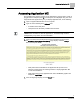
Introduction to Application MC Licensing NOTE: If you use Internet Explorer, do not select the Compatibility View options located in the IE Tools menu. Licensing If the graphics are left unmodified, only a Field Panel Web Server License is required. If you plan to use FINBuilder to modify any of the graphics, the graphic is considered a Kiosk graphic and either a Field Panel Web Server Service License or a Field Panel Web Server Host License is required. For more information, see the Kiosk User Guide.
Introduction to Application MC Application MC Prerequisites Application MC Prerequisites ● ● The Description field in the properties for each FLN device is properly configured. For more information, see the procedure Setting up the Description Property using WCIS [➙ 7]. Application MC files are deployed to the field panel from the Tools menu of Launch Pad. 6 Siemens Industry, Inc.
FLN Device and Network Set-up Setting up the Description Property using WCIS FLN Device and Network Set-up In order to create the hierarchy of the Application MC Navigation Tree, the FLN device description properties must be configured in a specific way. This section describes the format required for the description properties and outlines how to change the change the description to use a different control diagram.
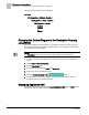
FLN Device and Network Set-up Changing the Control Diagram in the Description Property using WCIS The layout of the navigation tree is as follows: Buildings D1 (Suggestion – Building) - Required D2 (Suggestion – Floor) - Optional D3 (Suggestion – Room) Device1 Device2 … Device n Changing the Control Diagram in the Description Property using WCIS If the control diagram in the description of a Unit Vent controller is incorrect, and the Unit Vent was already discovered by Application MC, you can change the d
Accessing Application MC Accessing Application MC The Application MC graphic is hosted on the USB memory storage device, which is plugged into the USB port (Drive B) of a field panel, and displayed using one of the supported browser applications [➙ 4]. To display Application MC, do the following: 1. Open a supported Web browser on the computer. 2. Type one of the following in the Address field: – IP address of the field panel. – Field panel node name/Fully Qualified Domain Name.
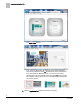
Accessing Application MC ⇨ The Login Page displays. ⇨ If you only have Application MC deployed and no other FIN Builder projects are published to Drive B, Application MC starts automatically. If you have other FIN Builder projects, once you are successfully authenticated, a list of thumbnail images from Drive B of the host field panel displays. Moving the cursor over a thumbnail image displays the name of the graphic. 5. Click the Application MC graphic thumbnail, if necessary. 10 Siemens Industry, Inc.
User Interface Navigation Overview Deploying Application MC User Interface Navigation Overview The following figure shows the default Application MC user interface. Figure 1: Application MC User Interface. 1 Title Pane. The Title Pane contains the Alarm Report button, the Application MC User Guide button, and the Logoff button. 2 Alarm Report button. Generates an alarm report. 3 Application MC User Guide button. Opens the user documentation. 4 Logoff button. Logs off the user. 5 Navigation Pane.
User Interface Navigation Overview Navigation Tree Navigation Tree The Navigation Tree displays in the Navigation Pane on the left side of Application MC. The Navigation Tree structure is based on the Description properties of the host panel’s FLN devices. For more information, see the Setting up the Description Property using WCIS [➙ 7] section. Expansion arrows allow you to expand and contract each level of the tree. Icons representing the application type are displayed for each FLN Device.
User Interface Navigation Overview Navigation Tree To clear the search criteria, click the Clear (x) button. The navigation tree collapses. Creating and Refreshing the Navigation Tree To create or refresh the Navigation Tree, click the Update Navigation Tree button. The Navigation Tree is updated to include devices that have been added to or removed from the host field panel since the last Update Navigation Tree operation. 13 Siemens Industry, Inc.
User Interface Navigation Overview Accessing the FLN Graphic Accessing the FLN Graphic An application graphic is displayed in the Application Graphics pane when you select an FLN device in the Navigation Tree. The Application Number displays in the graphic header. As the graphic is loading, a progress bar displays: Once the graphic has loaded, the progress bar indicates completion: A graphic is not fully loaded until the background color of all value labels is white. 14 Siemens Industry, Inc.
User Interface Navigation Overview Accessing the FLN Graphic Figure 2: Graphic in the Process of Loading. Figure 3: Graphic Finished Loading. The application graphic is populated with data from the selected device. Any objects on the graphic which cannot be resolved with data from the device will display the error NaN (Not a Number). 15 Siemens Industry, Inc.
User Interface Navigation Overview Accessing the FLN Graphic Points that are Failed display with an orange background. Figure 4: Graphic with Failed Point. If the selected device has no available graphic, the following image displays: Figure 5: Selected Device has no Graphic. 16 Siemens Industry, Inc.
Viewing and Commanding Points Viewing and Commanding Points NOTE: You must have Point Command or Point Edit permission to command the value of device points from an Application MC graphic. Certain points can be commanded from an application graphic. ● Points that are non-commandable are designed to prevent damage to equipment. ● Commandable points display with a green border when the cursor is moved over them. 17 Siemens Industry, Inc.
Displaying the Application Notes Displaying the Application Notes To display the Application Notes, click the Application Notes button on the application graphic. 18 Siemens Industry, Inc.
Viewing/Acknowledging Alarms Viewing/Acknowledging Alarms The ALARMS button in the Application MC Title pane displays an Alarm Report. You must be logged in with Alarm Read Only or higher permission to view the Alarm Report. To view the Alarm Report, click the ALARMS button. The report displays a list of objects from the host field panel that are currently in the unacknowledged alarm state. 2 3 4 5 6 7 8 9 1 1 Host field panel 2 Alarms button. Displays the point in alarm. 3 Point Name column.
Viewing/Acknowledging Alarms To view the alarm event details, click the Event Details button. A pop-up displays the alarm event details. To acknowledge an alarm, click the Acknowledge button. An alarm acknowledgement is sent to the field panel. A progress indicator displays. Once the alarm is acknowledged, it is removed from the Alarm Grid. NOTE: You must be logged in with Alarm Command or higher permission to acknowledge an alarm. Logging Off Click the Logoff button to properly close the graphic.
VAV Balancing and Heat Pump Configuration for Applications VAV Balancing and Heat Pump Configuration for Applications Flow-related points can be accessed from the configuration drop-down window in VAV or Heat Pump applications, such as Terminal Box, VAV with Variable Speed Drive, Dual Duct, and Heat Pump controllers. To access the drop-down window, click the window handle. To close the window, click the handle again. 21 Siemens Industry, Inc.
Customizing Application MC Accessing the FLN Graphic Customizing Application MC The Application MC FIN Builder project is a combination of several FIN Builder components. The main .finp file contains components and logic for the Title pane, Navigation pane, and Application Graphic pane. In addition, app_NNNN.FINP files (where NNNN is the FLN device’s application number) contain the application graphics for each supported FLN device application. To customize Application MC.
Customizing Application MC Accessing the FLN Graphic NOTE: Do not select Continue, which will relativize the graphic to the original field panel used for creation. The graphic will not function properly once it is published to the destination panel. 6. Double-click the cell under the New Host column and enter the IP address of the field panel where you plan to publish the graphic. 7. Click Continue. 8. Make modifications to the graphic. 9.
Customizing Application MC Application MC Mapping File Application MC Mapping File The Application MC mapping file is an XML-formatted file that Application MC uses to determine which graphic, icon, and Application Notes document to display for each application. The mapping file may also be used to add customized applications to the range of supported applications. The mapping file contains an [Application] element for each application.
Customizing Application MC Modifying the Application MC Mapping File Figure 6: Application MC Mapping File Locations. 1 The ApplicationMC_Mapping.xml file is deployed to the B:\FIN folder of the target field panel. Once Application MC has been deployed, you can remove the USB (B:) drive from the field panel and connect it to the computer. When finished with modifications, the USB drive can be removed from the computer and returned to the field panel.
Customizing Application MC Modifying the Application MC Mapping File Displaying the Default Graphic for a Customized Application Follow this workflow if you have made modifications that result in a new application number and you would like to use the default graphic supplied with Application MC for the original application number. For example, you have added additional points or PPCL to a PTEC device with an original application number of 6575 and have now assigned it a custom application number of 12575.
Customizing Application MC Modifying the Application MC Mapping File Displaying a Customized Graphic for a Default Application Follow this workflow if you have modified the default graphic or have created a FINBuilder custom graphic for one of the standard applications deployed with Application MC. For example, you have modified the application graphic for Application 6575. 1. Verify that you have deployed Application MC to the field panel. 2. Remove the USB (Drive B) from the field panel. 3.
Customizing Application MC Modifying the Application MC Mapping File Customizing the Icon Displayed in the Navigation Tree Icons are supplied with Application MC for the following application types: ● Fan Coil ● Heat Pump ● Unit Vent ● VAV ● AHU This icon is displayed in the Navigation Tree and indicates the application type (i.e. Unit Vent, Heat Pump, and so on.) CAUTION If creating a custom icon, each icon must be a 69 x 69 pixel .png image for the Navigation Tree to display correctly.
Customizing Application MC Modifying the Application MC Mapping File Icons folder and the mapping file is being changed to use that icon for Application 13000. 9. Save the XML file to the FIN folder in the USB drive. 10. Put the USB drive back into the field panel. Customizing the Application Note for an Application The most current version of Application Notes at the time of release is included in the Application MC deployment.
Customizing Application MC Modifying the Application MC Mapping File 5. Open the ApplicationMC_Mapping.xml file with your preferred text/XML editor. 6. In the XML file, navigate to the desired [Applicatio]> element. 7. Update the ApplicationGuide property to the name of your customized Application Notes file. In this example, Application Note APP_13000_PDF.PDF has been added to the DOCS folder and the mapping file has been changed to use that Application Note for Application 13000. 8.
Appendix A - Troubleshooting and Error Management Appendix A - Troubleshooting and Error Management ● ● ● ● ● ● ● BACnet Field Panel Web Server must be enabled. Appropriate licenses must be installed. Panel can be pinged successfully using the ping command. Applications must not be failed. Failed points display as orange. The ApplicationMC_Mapping.xml file is up-to-date with custom applications. The ApplicationMC_Mapping.xml is free of formatting errors. 31 Siemens Industry, Inc.
Issued by Siemens Industry, Inc. Building Technologies Division 1000 Deerfield Pkwy Buffalo Grove IL 60089 Tel. +1 847-215-1000 Document ID A6V10574894 Edition 2017-06-30 © Siemens Industry, Inc., 2017 Technical specifications and availability subject to change without notice.