
Installation Instructions

Installation Instructions
Document No. 545-432
Rev. 5, September, 2002
SCU Controller Board (Version 5)
Item Number 545-432-05 Page 1 of 4
Product Description
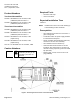
The SCU V5 controller board (Figure 1) is available
in seven configurations: six APOGEE and one pre-
APOGEE.
The controller board has two man-machine interface
(MMI) ports: the MMI and the MMI MODEM. Each
port comes with a quick-connect, RJ-11 jack. Use
these ports to connect to an operator terminal,
printer, or a modem approved by Siemens Building
Technologies.
The memory board slides into the controller board
bracket. The memory board’s flash read-only
memory (ROM) contains the firmware that controls
the SCU controller board.
The point board is positioned beneath the controller
board by standoffs. A ribbon cable electrically
connects the two boards. The point board contains
circuitry to connect to analog input (Al), analog
output (AO), digital input (DI), and digital output (DO)
points.
APOGEE Assemblies
Two-board Assembly (8 MB or 6 MB)
The APOGEE two-board assembly is used when
replacing existing pre-APOGEE V4 controllers. It
consists of the following components (Figure 1):
• SCU V5 controller board
• Memory board (8 MB or 6 MB total memory)
with 2.x firmware
Three-board Assembly (8 MB or 6 MB)
The APOGEE three-board assembly is used when
replacing existing pre-APOGEE V3 or earlier
controller boards with APOGEE V5. It consists of the
following components (Figure 1):
• SCU V5 controller board
• Memory board (8 MB or 6 MB total memory)
with 2.x firmware
• V4 point board
Pre-APOGEE Assembly
The pre-APOGEE three-board assembly is used
when replacing existing V3 or earlier controller
boards without upgrading to APOGEE firmware. It
consists of the following components (Figure 1):
• SCU V5 controller board
• Memory board (3 MB total memory) with 12.51
firmware
• V4 point board
FLN0046R1
MEMORY
BOARD
POINT
BOARD
CONTROLLER
BOARD
BATTERY
GROUND
WIRE
STATUSBST
BATT
LOW
POINT BOARD
RIBBON CABLE
5 VOLT ADJ
MMI PORT
MMI MODEM PORT
LISTED
CUS
¤
Underwriters Laboratories Inc.
Smoke Control System Equipment Subassembly
Also suitable for use as:
Energy Management Equipment Subassembly
Also suitable for use as:
Signal System Unit Equipment Subassembly
Also suitable for use as:
Process Management Equipment Subassembly
ISSUE NO. :AG-8256
545765032290015
WARNING:
Power must be ON
when replacing the
battery, otherwise
the cabinet will
coldstart.
Product Part No.
Refer to Installation Instructions, Part No.
BPS
(
Bits per second
)
Memory
FLN1
FLN2
FLN3
Modem
MMI
MMI
BLN
TIU
Enabled
BLN #
Controller Board
Field Panel No./Name
Warning:
Risk of static discharge.
Turn OFF power beforeremoving or servicing
boards. Use ESD wrist strap when servicing unit.
MMI
Port
MMI
Modem
Port
PART NO.
545 489
For use with System 600 as part of an
engineered smoke control system in accordance
with NFPA 92A. Refer to installation instructions.
PART NOS. 125-1890 Rev. 20 AND 125-1806 Rev.3
N474
Figure 1. SCU Version 5 Controller Board.