
Installation Instructions

Installation Instructions
Document No. 540-212
July 22, 2009
Pneumatic Output Module
Item No. 540-212, Rev, DA
Information in this publication is based on current specifications. The company reserves the right to make changes in specifications and
models as design improvements are introduced. Product or company names mentioned herein may be the trademarks of their respective
owners. © 2009 Siemens Building Technologies, Inc.
Siemens Building Technologies, Inc.
Industry Sector
1000 Deerfield Parkway
Buffalo Grove, IL 60089-4513
U.S.A.
Your feedback is important to us. If you have
comments about this document, please send them
to sbt_technical.editor.us.sbt@siemens.com
Document No. 540-212
Printed in the U.S.A.
Page 1 of 1
Product Description
The Pneumatic Output Module is the interface
between the controller and the pneumatic controller
device.
Product Numbers
540-166
540-167
Required Tools
Pliers, side slotted type.
Expected Installation Time
12 minutes
Installation
1. The Pneumatic Output Module should be
located near the location of the controller. If the
controller is not installed, identify where it is to
be located.
2. Pull the supply (S) air line to the location of the
controller, allowing enough slack to reach the
controller.
3. Pipe or repipe (if required) the terminal
equipment per the defined application.
4. Connect the supply air line to the supply (S)
port on the Pneumatic Output Module. See
Figure 2.
5. Connect the air line from the controlled device
to the return (R) port on the Pneumatic Output
Module. See Figure 2.
The Installation is complete.
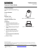
VP0165R1
Figure 1. Pneumatic Output Module (540-167).
VP0164R1
RS
Figure 2. Return (R) and Supply (S) Ports.