
Installation Instructions

Installation Instructions
Document No. 586-148-05
July, 2002
Point Expansion Modules
Page 1 of 3
Product Description
Point Expansion Modules (PXM) are a collection of
devices that expand the number of points controlled
and monitored on the MEC Expansion Bus or on the
FLN.
Analog and Digital Point Expansion Modules are
compatible with the MEC Expansion Bus and the FLN
(P1) from any APOGEE or pre-APOGEE field panel
equipped with an FLN.
For more information on Point Expansion Modules
hardware and applications, see the
Modular
Equipment Controller Owner’s Manual
(125-2183).
Product Numbers
549-210 Digital Point Expansion, HOA Ready, 8 DI, 4 DO
549-211 Digital Point Expansion with HOA, 8 DI, 4 DO
549-212 Digital Point Expansion, HOA Ready, 4 DI, 4 DO
549-213 Digital Point Expansion with HOA, 4 DI, 4 DO
549-209 Analog Point Expansion, 8 AI
549-214 Analog Point Expansion, HOA Ready, 4 AI, 4 AO
549-215 Analog Point Expansion with HOA, 4 AI, 4 AO
Warning/Caution Notations
WARNING:
Personal injury or property
damage may occur if you do not
follow the procedure as specified.
CAUTION:
Equipment damage or loss of
data may occur if you do not
follow the procedure as specified.
Required Tools and Material
•
Wire stripper/side cutters
•
Phillips screwdriver
•
Level
•
Tape measure
•
Digital multi-meter (DMM)
To mount on a surface
•
Electric drill
•
Black marker
•
Four No. 8 × 3/8 self-tapping Phillips screws
To mount on concrete or masonry
•
Masonry drill bit
•
Four lead wall anchors
Expected Installation Time
20 minutes
E
22
24
21
1
9
18
20
23
26
28
25
27
1
7
H
N
S
+
-
RX
STATUS
TX
FLN / EXP
MEC0074R2
DIGITAL INPUT
CONNECTORS
EXPANSION
CONNECTOR
STATUS LEDS
DIGITAL OUTPUT
CONNECTORS
C17
DO9
NO 18
NC 19
C20
DO10
NO 21
NC 22
C23
DO11
NO 24
NC 25
C26
DO12
NO 27
NC 28
POWER
CONNECTOR
1
DI1
2
3
DI2
4
5
DI3
6
7
DI4
8
9
DI5
10
11
DI6
12
13
DI7
14
15
DI8
16
0
A
0
A
0
A
0
A
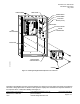
Figure 1. Digital Point Expansion
(pictured with HOA control switches).