Kiosk Mode Including FIN Builder Graphic Support and Application MC User Guide A6V10435686 2017-06-30 Building Technologies A6V10435686, Rev.
Copyright Notice Cyber security disclaimer Copyright Notice Notice Document information is subject to change without notice by Siemens Industry, Inc. Companies, names, and various data used in examples are fictitious unless otherwise noted. No part of this document may be reproduced or transmitted in any form or by any means, electronic or mechanical, for any purpose, without the express written permission of Siemens Industry, Inc.
Table of Contents FIN Builder Graphics Tool .................................................................................................... 5 FIN Builder Graphics Tool Overview .................................................................................... 5 FIN Builder Prerequisites................................................................................................. 5 Using the FIN Builder Graphics Tool .................................................................................
Appendix A - Troubleshooting and Error Management ...................................................... 78 4 Siemens Industry, Inc.
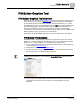
FIN Builder Graphics Tool FIN Builder Graphics Tool Overview FIN Builder Graphics Tool FIN Builder Graphics Tool Overview FIN Builder is a J2 Innovations (www.j2inn.com) graphics creation and publication tool. Using the Siemens Connector application, many customized features of FIN Builder are accessible through the Siemens controllers on Firmware Revision 3.3.1 or later. FIN Builder allows you to create FIN Builder projects (.finp files), binding complex data to sophisticated graphics.
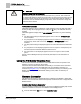
FIN Builder Graphics Tool Using the FIN Builder Graphics Tool CAUTION Frequent Polling May Tax the System A FIN Builder graphic's default poll rate interval is one (1) second. This means that the graphic will attempt to obtain the current value for each bound point every second. For some systems, this may be too frequent. The recommended poll rate interval is 15 seconds. See the Default Settings [➙ 35] section of this document to change the poll rate from the default.
FIN Builder Graphics Tool Using the FIN Builder Graphics Tool A Select Library window displays. 2. Browse to the location where you have stored the Siemens Connector file. Doubleclick the FINSiemensLibrary.flb file, or highlight the file and then click Open. Successful new installation displays. Click OK. When upgrading, a successful replacement/upgrade displays. Click OK, close FIN Builder and then restart the application. 7 Siemens Industry, Inc.
FIN Builder Graphics Tool Using the FIN Builder Graphics Tool CAUTION FIN Builder Shuts Down Automatically If this installation of FIN Builder starts to run and then shuts down automatically, you may need to delete the FINSiemensLibrary.flb file in the Network folder from the AIR cache: 1. Exit FIN Builder. 2. Navigate to: C:\Users\\AppData\Roaming\com.j2inn.FinBuilde \Local Store\system\Network. 3. Locate and delete the FINSiemensLibrary.flb file. 4. Start FIN Builder. 5.
FIN Builder Graphics Tool Using the FIN Builder Graphics Tool 2. In the Mapping & Equipment window, the VALUE field of the Siemens Connector Revision object displays the revision string of the Siemens Connector Revision currently installed. 9 Siemens Industry, Inc.
FIN Builder Graphics Tool Using the FIN Builder Graphics Tool Viewing at the Field Panel When the Siemens Connector Revision graphic files are uploaded to the Drive B:\FIN directory you will see the thumbnail of the graphic in Kiosk mode. NOTE: Web browsers such as Firefox or Internet Explorer may have cached an older version of FINSiemensLibrary.flb. If the Siemens Connector Revision graphic does not display a revision string that matches the version stored in the Drive B:\FIN directory, clear the cache o
FIN Builder Graphics Tool Using the FIN Builder Graphics Tool Getting the Siemens Connector Revision Graphic Downloading from Partner Extranet Site 1. Open Partner Extranet web site and navigate to \Products\Building Automation, Engineering Tools section, and then select FIN Builder. 2. From the Resource Center, right-click FIN Builder Connector (.flb – 1 MB) and then extract FIN_Lib.zip file. The following files are extracted: – FINSiemensLibrary.flb – Siemens Connector Installation ReadMe.pdf – \FIN
FIN Builder Graphics Tool Using the FIN Builder Graphics Tool Connecting to a Device Once the Siemens Connector is installed, you can add Siemens field panels to FIN Builder. This will allow you to connect to those devices and bind information from those devices to components in FIN Builder graphics. To connect a device to FIN Builder: 1. From the Devices menu, move your cursor over Available Devices and select Add Device. A New Device selection displays. Select New Device. 2.
FIN Builder Graphics Tool Using the FIN Builder Graphics Tool 3. Click the Connect button. Once connected, the device and associated data display in the device tree, including: • Local points • Trend log objects • Schedule, calendar, and command objects • FIN projects • Status values • Permissions • Alarm counts 13 Siemens Industry, Inc.
FIN Builder Graphics Tool Using the FIN Builder Graphics Tool NOTE: If you connect to a device with Firmware Revision 3.2.5 or earlier, data from that device will not be available in the device tree. If FIN Builder cannot connect to a device, a Login Failed error message displays: Accessing Data on Multiple FLN Types FIN Builder supports multiple FLN device types. Each controller can support at least one type of FLN device (BACnet MS/TP or IP, P1, or Integration).
FIN Builder Graphics Tool Using the FIN Builder Graphics Tool Mapping Siemens Device Data to FIN Builder Graphical Components Through the Siemens Connector, Siemens device data is made available for mapping to FIN Builder graphical components. The available device data includes the following: ● Point Data ● Permissions ● Alarm Counts ● Alarm Data ● FLN Discovery (Navigation) Data Point Data Panel point data is located in the Local folder of each device.
FIN Builder Graphics Tool Using the FIN Builder Graphics Tool NOTE: If the Editor's Palette is not available in Basic Mode, set Advanced Mode as your default in the Canvas Properties. See the following Figure. Permissions The Permission objects align with the User Account permissions in the field panel. Each object represents the permissions of the user (No Access, Read Only, Command, and Edit) currently logged into the field panel hosting the displayed graphic.
FIN Builder Graphics Tool Using the FIN Builder Graphics Tool In FIN Builder, they are stored as enumerated values: In the above example, the Point Access permission of the user currently logged in is Command. Alarm Counts Alarm Counts are numeric values in FIN Builder that represent the values of the corresponding resident points in the field panel. Alarm Count data can be used with FIN Builder Actions or displayed directly on the graphic. Alarm Counts can be bound to Labels or Numeric Editors.
FIN Builder Graphics Tool Using the FIN Builder Graphics Tool Adding an Alarm Grid Update Timer 1. Select the Timer component from the Controls palette and add it to your graphic. You may want to place the component close to the Alarm Grid for readability. The Timer will not be visible once the graphic is published. 2. In the Timer Properties, do the following: – Change the Name of the Timer to ALARM_GRID_TIMER. – Verify that AUTO_START is selected. – Change the INTERVAL to 60 seconds. 3.
FIN Builder Graphics Tool Using the FIN Builder Graphics Tool 4. Select Alarms as the point to refresh. 5. Save and publish the graphic. The Alarm Data will be refreshed at the rate configured in the Timer Interval property. FLN Discovery (Navigation) Data FLN Discovery data includes a list of FLN devices that have been added to the host panel database, and have a properly formatted description property (see the Application MC section for more information).
FIN Builder Graphics Tool Using the FIN Builder Graphics Tool If a device (other than the device hosting the graphic) fails after the graphic is opened, this is seen as a change in status. The graphic components that are bound to objects in this device will not automatically display as degraded unless specific settings have been selected in the graphic properties.
FIN Builder Graphics Tool Using the FIN Builder Graphics Tool ● For the Alpha property, the Status to Simple feature allows you to select the Alpha level for each status. Examples The following examples outline how to map the Failed state of an object to the Fault state in FIN Builder. Example 1: Degrading a Label Component In this example, a Label component is set up to degrade when the device containing the point bound to that component point is Failed.
FIN Builder Graphics Tool Using the FIN Builder Graphics Tool Figure 1: Degrading a Label Component - Binding a Label Component to the Device Point. 3. Bind this same point to the Alpha property. Figure 2: Degrading a Label Component - Binding the Point to the Alpha Property. 4. Select the Alpha property. 5. From the drop-down menu at the bottom of the screen, select Status to Simple. 22 Siemens Industry, Inc.
FIN Builder Graphics Tool Using the FIN Builder Graphics Tool Figure 3: Degrading a Label Component - Selecting Status to Simple for the Alpha Property. The menu to adjust the Alpha level options for each status is displayed. 6. To degrade the Label to 15% Alpha when the point goes into a Failed state, select the slider for Fault and drag it to an Alpha setting of 15.00. Figure 4: Degrading a Label Component - Adjusting the Label Display when the Point is Failed. 23 Siemens Industry, Inc.
FIN Builder Graphics Tool Using the FIN Builder Graphics Tool NOTE: Any value can be selected for the Fault state. However, a low value, such as 15%, is recommended so that the failure or other condition is evident to the user. 7. Leave the other Alpha level options unchanged and click the Apply button. 8. Repeat this procedure for all bound components that you want to display as degraded when the point (or device) they are bound to fails.
FIN Builder Graphics Tool Using the FIN Builder Graphics Tool Figure 6: Degrading a Gauge Component - Binding the Point to the Alpha Property. 4. Select the Alpha property. 5. From the drop-down menu at the bottom of the screen, select Status to Simple. Figure 7: Degrading a Gauge Component - Selecting Status to Simple for the Alpha Property. The menu to adjust the Alpha level options for each status is displayed. 6.
FIN Builder Graphics Tool Using the FIN Builder Graphics Tool Figure 8: Degrading a Gauge Component - Adjusting the Gauge Display when the Point is Failed. NOTE: Any value can be selected for the Fault state. However, a low value, such as 15%, is recommended so that the failure or other condition is evident to the user. 7. Leave the other Alpha level options unchanged and click the Apply button. 8.
FIN Builder Graphics Tool Using the FIN Builder Graphics Tool Figure 9: Changing the Background Color of a Label - Adding a Shape to the Graphic. 2. Add a Label Component to your graphic. 3. Bind it to the desired device point. In our example, we are using an FLN device point AOV1. 4. Center the Label in the Rectangle. Figure 10: Changing the Background Color of a Label - Binding the Label Component to the Device Point. 5. Select the Rectangle.
FIN Builder Graphics Tool Using the FIN Builder Graphics Tool Figure 12: Changing the Background Color of a Label - Selecting Status to Simple for the Fill Property. The menu to select the background fill color for each status is displayed. 7. To change the fill color of the rectangle when the point goes into a Failed state, select a color for the Fault state. In this example, red is chosen for the Fault state. 28 Siemens Industry, Inc.
FIN Builder Graphics Tool Using the FIN Builder Graphics Tool Figure 13: Changing the Background Color of a Label - Selecting the Color to Display when the Point is Failed. 8. Click the Apply button. 9. Repeat this procedure for all bound components that you want to change color when the point (or device) they are bound to fails.
FIN Builder Graphics Tool Using the FIN Builder Graphics Tool Using the Greenleaf Component While you are in FIN Builder's design mode, you can drag the model from your local computer to the canvas of an open graphic. The first time you use the model in a FIN Builder graphic, the model is automatically saved to your FIN Builder Models folder for use in other graphics. The Greenleaf model can be dragged from the Library/Models folder and dropped onto the FIN Builder graphic. 30 Siemens Industry, Inc.
FIN Builder Graphics Tool Using the FIN Builder Graphics Tool The model's default properties are as shown: 31 Siemens Industry, Inc.
FIN Builder Graphics Tool Using the FIN Builder Graphics Tool When the model is bound to one of the available Greenleaf objects, the model will indicate the energy efficiency state as determined by the DXR energy efficiency algorithm. Greenleaf Object Description Indication Gray DXR energy efficiency is in an undefined state or that there is a connection or binding issue with the equipment or graphic. Degraded gray The graphic has not yet received a value from the device for the bound point.
FIN Builder Graphics Tool Using the FIN Builder Graphics Tool Relativizing MS/TP Devices You can relativize graphics from one BACnet FLN Device to other BACnet FLN Devices. With Siemens BACnet devices the application point mappings are similar across devices. For example, Room Temperature always has an object identifier of 0,4. Therefore, the points will relativize easily from device to device. Relativizing ALN and FLN Devices This is strongly NOT recommended.
FIN Builder Graphics Tool Using the FIN Builder Graphics Tool 3. Drag the appropriate components onto the graphic canvas. In the following example, three gauges are being used. 4. Drag and drop the points from the Mapping pane and bind them to the graphical component that is being relativized. 5. Repeat Step 4 for all points. 6. Click the Relativize to drop-down arrow at the top of the Mapping pane and then select the device that contains the points you dropped into the Mapping pane in Step 2.
FIN Builder Graphics Tool Using the FIN Builder Graphics Tool A drop-down list displays. 7. Use the checkmarks to the right of the points to select all the points that you want to relativize, or deslect all the points that you do not want to relativize. 8. Click the blue checkmark in the upper right corner to indicate that you are done. The Mapping window displays the relativized points. The Equipment window displays the unrelativized points, organized by device folder.
FIN Builder Graphics Tool Using the FIN Builder Graphics Tool Logoff Management To ensure proper logoff management of Web sessions at the field panel, a logoff button should be added to each graphic. This button is available in the FIN Builder Models folder on the Siemens Graphics Library SharePoint site (https://projectsindustry.usa.siemens.com/bt/graphicslib/Graphics%20Library/Forms/AllItems.aspx), or you can create one. Contact your Siemens representative for assistance.
FIN Builder Graphics Tool Using the FIN Builder Graphics Tool 9. Publish the graphic to the host panel. 10. Using a Web browser, connect to the host panel. 11. From the Landing Page, select Kiosk and open the graphic you just published. 12. Verify that selecting the Logoff button returns you to the Landing Page. Creating a Logoff Button Model To create a Logoff button that returns you to the Landing Page: 1. Place a Button component from the Controls Palette on the canvas. 2.
FIN Builder Graphics Tool Using the FIN Builder Graphics Tool 5. Select the Button component. 6. To the right of the Actions drop-down menu, select the button to add an action. 7. Move your cursor over the Click option, then Network, and then select Log off Action. 8. From the Select Point drop-down list, select the point you created. 9. Select the check box to the right of the newly added point. Leave the delay at 0 milliseconds. 10. Add another action by clicking the button. 11.
FIN Builder Graphics Tool Using the FIN Builder Graphics Tool 12. In the Actions drop-down menu, select Same Page. 13. Click the settings caption button to open the WebPage Settings property box. Enter /wsroot/index.html in the TARGET URL field. 14. Check the box to the right of the Actions drop-down menu and select 200 milliseconds. 15. Drag-and-drop the point you created from the Mapping pane onto the button.
FIN Builder Graphics Tool Using the FIN Builder Graphics Tool 16. Name the component. 17. Click Save and save to the Models folder. Publishing a Project (Graphic) Graphics, referred to in FIN Builder as FIN Builder Project files (.finp), must be published to Drive B on the field panel. NOTE: Multiple users publishing to the same panel at the same time is not recommended; this may reduce PPCL performance and may cause publication to fail.
FIN Builder Graphics Tool Using the FIN Builder Graphics Tool A list of field panels to which the project can be published displays. FIN Builder projects can only be published to Drive B of PXC Modular or PXC-36 controllers with Firmware Revision 3.3 or later. 2. Expand the panel to display Drive B. 3. Select Drive B on this panel as the location to publish the project. 4. Verify that the FIN HOST: selection is Siemens. 5. Provide a PUBLISH NAME for the project. 6. Select Publish.
FIN Builder Graphics Tool Using the FIN Builder Graphics Tool FIN Builder creates a thumbnail for each project and publishes it with the project. Thumbnail files are named ProjectName.jpg and are stored in the B:\FIN\Projects folder along with the ProjectName.finp file. When displaying a project from within a browser, thumbnails display and can be used to select which project to display.
FIN Builder Graphics Tool Using the FIN Builder Graphics Tool To make modifications to a FIN Builder project: 1. Connect to the field panel in FIN Builder. 2. From the Devices pane, expand the panel. 3. Expand FIN Projects. 4. Right-click on the project you want to edit and select Import FINP. 43 Siemens Industry, Inc.
FIN Builder Graphics Tool Using the FIN Builder Graphics Tool 5. Do one of the following: – If you plan to publish the modified project to the same field panel, click Continue. – If you plan to publish the modified project to a different panel, enter the destination panel IP Address in the New Host field. 44 Siemens Industry, Inc.
FIN Builder Graphics Tool Using the FIN Builder Graphics Tool 6. Make modifications to the project and click Publish. 7. To save the project for backup purposes, select Save As from the File menu. Deleting FIN Projects (Graphics) FIN Projects (.finp files) include the graphic as well as all the assets used in that graphic. Assets include all elements of the graphic including FIN Builder graphical components, models, and external images. Assets are not shared among FIN projects.
FIN Builder Graphics Tool Using the FIN Builder Graphics Tool 3. Highlight the graphic you want to delete and click the Delete button. 46 Siemens Industry, Inc.
FIN Builder Graphics Tool Using the FIN Builder Graphics Tool 4. Click the Confirm button to confirm the deletion. 47 Siemens Industry, Inc.
FIN Builder Graphics Tool Using the FIN Builder Graphics Tool Viewing a FIN Builder Graphic in Kiosk Mode 1. Open a supported Web browser on the computer. 2. Type one of the following in the Address field: – IP address of the field panel. – Field panel node name/Fully Qualified Domain Name. NOTE: The browser must be configured to ignore the proxy settings for the panel names and/or IP addresses. See the Troubleshooting [➙ 50] section for more information. 3.
FIN Builder Graphics Tool Using the FIN Builder Graphics Tool ⇨ The Login Page displays. ⇨ Once you are successfully authenticated, a list of thumbnail images from Drive B of the host field panel displays. Moving the cursor over a thumbnail image displays the name of the graphic. ⇨ If no thumbnail image exists for the graphic, a generic FIN thumbnail image displays. 49 Siemens Industry, Inc.
FIN Builder Graphics Tool Troubleshooting 5. Click a thumbnail to display that graphic. If only one graphic exists, it will display automatically. NOTE: Thumbnails are created during publication by FIN Builder. See the Saving and Publishing a Project section of this document. If you manually delete a thumbnail image, the project must be republished in order to recreate the thumbnail. NOTE: Kiosk Mode does not support FINlite graphics. 6. Click the Logoff button to properly close the graphic.
FIN Builder Graphics Tool Troubleshooting Determining the Current FIN Builder Field Panel License FIN Builder displays the most comprehensive FPWeb license installed on a connected panel. To view this license information: 1. Connect to the field panel in FIN Builder. 2. From the Devices pane, right-click the panel and select License and Projects. License information displays along with a list of the graphics currently published to the field panel.
FIN Builder Graphics Tool Troubleshooting 52 Siemens Industry, Inc.
Application MC Introduction to Application MC Application MC Introduction to Application MC Application MC (Monitor & Control) is a FIN Builder Project that contains a Navigation Tree and application graphics for many of the available MS/TP FLN device applications.
Application MC Introduction to Application MC NOTE: If you use Internet Explorer, do not select the Compatibility View options located in the IE Tools menu. Licensing If the graphics are left unmodified, only a Field Panel Web Server License (LSMFPWEB) is required. If you plan to use FINBuilder to modify any of the graphics, the graphic is considered a Kiosk graphic and either a Field Panel Web Server Service License (LSM-FPWEBPL) or a Field Panel Web Server Host License (LSM-FPWEBPLHST) is required.
Application MC Accessing Application MC Application MC Prerequisites ● ● The Description field in the properties for each FLN device is properly configured. For more information, see the procedure Setting up the Description Property using WCIS [➙ 76]. Application MC files are deployed to the field panel from the Tools menu of Launch Pad.
Application MC Accessing Application MC ⇨ The Login Page displays. ⇨ If you only have Application MC deployed and no other FIN Builder projects are published to Drive B, Application MC starts automatically. If you have other FIN Builder projects, once you are successfully authenticated, a list of thumbnail images from Drive B of the host field panel displays. Moving the cursor over a thumbnail image displays the name of the graphic. 56 Siemens Industry, Inc.
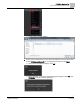
Application MC User Interface Navigation Overview 5. Click the Application MC graphic thumbnail, if necessary. User Interface Navigation Overview The following figure shows the default Application MC user interface. Figure 14: Application MC User Interface. 1 Title Pane. The Title Pane contains the Alarm Report button, the Application MC User Guide button, and the Logoff button. 2 Alarm Report button. Generates an alarm report. 3 Application MC User Guide button. Opens the user documentation.
Application MC User Interface Navigation Overview Navigation Tree The Navigation Tree displays in the Navigation Pane on the left side of Application MC. The Navigation Tree structure is based on the Description properties of the host panel’s FLN devices. For more information, see the Setting up the Description Property using WCIS [➙ 76] section. Expansion arrows allow you to expand and contract each level of the tree. Icons representing the application type are displayed for each FLN Device.
Application MC User Interface Navigation Overview To clear the search criteria, click the Clear (x) button. The navigation tree collapses. Creating and Refreshing the Navigation Tree To create or refresh the Navigation Tree, click the Update Navigation Tree button. The Navigation Tree is updated to include devices that have been added to or removed from the host field panel since the last Update Navigation Tree operation. 59 Siemens Industry, Inc.
Application MC User Interface Navigation Overview 60 Siemens Industry, Inc.
Application MC User Interface Navigation Overview Accessing the FLN Graphic An application graphic is displayed in the Application Graphics pane when you select an FLN device in the Navigation Tree. The Application Number displays in the graphic header. As the graphic is loading, a progress bar displays: Once the graphic has loaded, the progress bar indicates completion: A graphic is not fully loaded until the background color of all value labels is white. 61 Siemens Industry, Inc.
Application MC User Interface Navigation Overview Figure 15: Graphic in the Process of Loading. Figure 16: Graphic Finished Loading. The application graphic is populated with data from the selected device. Any objects on the graphic which cannot be resolved with data from the device will display the error NaN (Not a Number). 62 Siemens Industry, Inc.
Application MC Viewing and Commanding Points Points that are Failed display with an orange background. Figure 17: Graphic with Failed Point. If the selected device has no available graphic, the following image displays: Figure 18: Selected Device has no Graphic. Viewing and Commanding Points NOTE: You must have Point Command or Point Edit permission to command the value of device points from an Application MC graphic. Certain points can be commanded from an application graphic.
Application MC Displaying the Application Notes ● Commandable points display with a green border when the cursor is moved over them. Displaying the Application Notes To display the Application Notes, click the Application Notes button on the application graphic. 64 Siemens Industry, Inc.
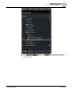
Application MC Viewing/Acknowledging Alarms Viewing/Acknowledging Alarms The ALARMS button in the Application MC Title pane displays an Alarm Report. You must be logged in with Alarm Read Only or higher permission to view the Alarm Report. To view the Alarm Report, click the ALARMS button. The report displays a list of objects from the host field panel that are currently in the unacknowledged alarm state. 2 3 4 5 6 7 8 9 1 1 Host field panel 2 Alarms button. Displays the point in alarm.
Application MC VAV Balancing and Heat Pump Configuration for Applications To view the alarm event details, click the Event Details button. A pop-up displays the alarm event details. To acknowledge an alarm, click the Acknowledge button. An alarm acknowledgement is sent to the field panel. A progress indicator displays. Once the alarm is acknowledged, it is removed from the Alarm Grid. NOTE: You must be logged in with Alarm Command or higher permission to acknowledge an alarm.
Application MC Customizing Application MC To close the window, click the handle again. Customizing Application MC The Application MC FIN Builder project is a combination of several FIN Builder components. The main .finp file contains components and logic for the Title pane, Navigation pane, and Application Graphic pane. In addition, app_NNNN.FINP files (where NNNN is the FLN device’s application number) contain the application graphics for each supported FLN device application.
Application MC Customizing Application MC 4. Wait for the FINP file to be uploaded from the panel. 5. Do one the following when the Change Hosts window displays: – Select Cancel to cancel the operation and close the graphic file. – Select Work Offline if you plan to modify the graphic without being connected to the host panel. NOTE: Do not select Continue, which will relativize the graphic to the original field panel used for creation.
Application MC Customizing Application MC 8. Make modifications to the graphic. 9. From the File menu, select Publish to publish the modified graphic to the desired field panel. WARNING Modifying the ApplicationMC.finp graphic is not recommended. This is the parent graphic for Application MC and it will be overwritten the next time Application MC is deployed.
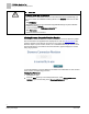
Application MC Customizing Application MC 1 ApplicationNumber. The application number that describes this element in the mapping file. 2 IconFile. The icon image that displays in the Navigation Tree to indicate the application type (i.e. Heat Pump, VAV, and so on.) 3 ApplicationGuide. The name of the Application Notes .pdf file that will display for the application. 4 ApplicationDescription. A short description displayed in the selection window during Application MC deployment. 5 GraphicName.
Application MC Customizing Application MC Figure 19: Application MC Mapping File Locations. 1 The ApplicationMC_Mapping.xml file is deployed to the B:\FIN folder of the target field panel. Once Application MC has been deployed, you can remove the USB (B:) drive from the field panel and connect it to the computer. When finished with modifications, the USB drive can be removed from the computer and returned to the field panel. 2 The BACKUP folder contains a Default_ApplicationMC_Mapping.
Application MC Customizing Application MC Displaying the Default Graphic for a Customized Application Follow this workflow if you have made modifications that result in a new application number and you would like to use the default graphic supplied with Application MC for the original application number. For example, you have added additional points or PPCL to a PTEC device with an original application number of 6575 and have now assigned it a custom application number of 12575.
Application MC Customizing Application MC Displaying a Customized Graphic for a Default Application Follow this workflow if you have modified the default graphic or have created a FINBuilder custom graphic for one of the standard applications deployed with Application MC. For example, you have modified the application graphic for Application 6575. 1. Verify that you have deployed Application MC to the field panel. 2. Remove the USB (Drive B) from the field panel. 3. Connect the USB drive to your computer.
Application MC Customizing Application MC Customizing the Icon Displayed in the Navigation Tree Icons are supplied with Application MC for the following application types: ● Fan Coil ● Heat Pump ● Unit Vent ● VAV ● AHU This icon is displayed in the Navigation Tree and indicates the application type (i.e. Unit Vent, Heat Pump, and so on.) CAUTION If creating a custom icon, each icon must be a 69 x 69 pixel .png image for the Navigation Tree to display correctly. Siemens Industry, Inc.
Application MC Customizing Application MC Icons folder and the mapping file is being changed to use that icon for Application 13000. 9. Save the XML file to the FIN folder in the USB drive. 10. Put the USB drive back into the field panel. Customizing the Application Note for an Application The most current version of Application Notes at the time of release is included in the Application MC deployment.
Application MC FLN Device and Network Set-up 5. Open the ApplicationMC_Mapping.xml file with your preferred text/XML editor. 6. In the XML file, navigate to the desired [Applicatio]> element. 7. Update the ApplicationGuide property to the name of your customized Application Notes file. In this example, Application Note APP_13000_PDF.PDF has been added to the DOCS folder and the mapping file has been changed to use that Application Note for Application 13000. 8.
Application MC FLN Device and Network Set-up ● (Optional) D3$# (the $# parameter is for Unit Vent applications only.) Since Unit Vent applications contain several Control Diagrams you need to specify which Control Diagram should display. Therefore, type $# where # is the number of the Control Diagram as specified in the Application Guide. For example, $2 would display Control Diagram 2 (Control Diagram 1 is the default). The following examples show correctly formatted Description fields: ● BUILDING1.
Application MC Appendix A - Troubleshooting and Error Management 7. To display the correct control diagram, select the Unit Vent with the changed description (even if it is already selected). Deploying Application MC Application MC is deployed by selecting Deploy Application MC from the Tools menu in Launch Pad. See the Launch Pad User Guide (145-1005) for more information. Appendix A - Troubleshooting and Error Management ● ● ● ● ● ● ● BACnet Field Panel Web Server must be enabled.
Issued by Siemens Industry, Inc. Building Technologies Division 1000 Deerfield Pkwy Buffalo Grove IL 60089 Tel. +1 847-215-1000 Document ID A6V10435686 Edition 2017-06-30 © Siemens Industry, Inc., 2017 Technical specifications and availability subject to change without notice.