
Installation Instructions

Installation Instruction
s
Document No. 545-405
Rev. 7, February, 2002
Point Module
Page 1 of 4
Product Description
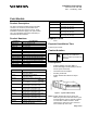
The Point Termination Module (PTM) assembly
consists of an electronic point module and a
termination block (see Figures 1 and 2). These
installation instructions apply to the point module
only. See Installation Instructions (545-404) for
termination block installation.
Product Numbers
Product No. Point Modules
PTM6.2P1K 2 AI, 1K Platinum RTD
PTM6.2N100K 2 AI, 100K Thermistor
PTM6.U10 2 AI, 0-10 Vdc
PTM6.21420 2 AI, 4-20 mA
PTM6.2D20 2 DI, Dry Contact
PTM6.4D20 4 DI, Dry Contact
PTM6.2D50 2 DI, Voltage Sensing, Isolated
PTM6.2C 2 DI, Pulse Accumulator
PTM6.2Y10S 2 AO, 0-10 Vdc
PTM6.2Y10S-M 2 AO, 0-10 Vdc with Manual Override
PTM6.2Y420 2 AO, 4-20 mA
PTM6.2Y420-M 2 AO, 4-20 mA with Manual Override
PTM6.1PSI20-M
1 AO—Pneumatic with Manual Overrid
e
PTM6.2Q250 2 DO, Contact
PTM6.2Q250-M 2 DO, Contact with Manual Override
Product No. Accessories
PTX6.H Replacement High Voltage
Termination Block
PTX6.L Replacement Low Voltage
Termination Block
545-021 Replacement AO-P Point module.
See
Installation Instructions
(545-406)
545-020 Replacement AO-P Connector Block.
See
Installation Instructions
(545-406)
545-040 Address Keys numbered 004 through
064 (16 keys in increments of 4)
545-041 Address Keys numbered 068 through
128 (16 keys in increments of 4)
545-042 Address Keys numbered 132 through
192 (16 keys in increments of 4)
545-043 Address Keys numbered 196 through
256 (16 keys in increments of 4)
545-044 Address Keys numbered 260 through
296 (10 keys in increments of 4)
545-053 Identification Labels (12 per sheet)
545-825 APOGEE Address Keys numbered
1 through 16 (16 keys)
Product No. Accessories
545-826 APOGEE Address Keys numbered
17 through 32 (16 keys)
545-827 APOGEE Address Keys numbered
33 through 48 (16 keys)
545-828 APOGEE Address Keys numbered
49 through 64 (16 keys)
545-829 APOGEE Address Keys numbered
65 through 80 (16 keys)
Required Tools
•
None
Expected Installation Time
6 minutes per module
Caution Notation
CAUTION
:
Equipment damage or loss of
data may occur if the user
does not follow a procedure as
specified.
Prerequisites
•
Modular Building Controller (MBC) or
Remote Building Controller (RBC) mounted
and AC power connected.
•
Termination blocks installed.
•
All wiring terminated.
•
Module identification labels and layout
sheet.
Figure 1. Typical PTM Assembly.
NOTE:
Module identification layout sheets and
labels are generated in the field office by the
Field Workstation and are typically supplied
for each MBC or RBC enclosure. These
sheets list the devices that are connected
and controlled by each PTM.