BACnet Field Panel Web Server User Guide 125-3584 2017-07-31 Building Technologies
Copyright Notice Cyber security disclaimer Copyright Notice Notice Document information is subject to change without notice by Siemens Industry, Inc. Companies, names, and various data used in examples are fictitious unless otherwise noted. No part of this document may be reproduced or transmitted in any form or by any means, electronic or mechanical, for any purpose, without the express written permission of Siemens Industry, Inc.
Table of Contents How to Use This Manual....................................................................................................... 7 Related Documents .............................................................................................................. 7 Symbols Used in this Manual ............................................................................................... 7 Manual Conventions .........................................................................................
Commanding Point Values ............................................................................................ 47 Disabling and Re-enabling a Point (Out-of-Service) ..................................................... 48 Resetting the Totalized Value ........................................................................................ 49 Priority Arrays ................................................................................................................ 49 Chapter 6 - Graphics View.....
Using the Command Object Editor .............................................................................. 107 Using the Calendar Object Editor ................................................................................ 109 Event Enrollment .............................................................................................................. 112 Event Enrollment Overview .........................................................................................
Launching the FINlite Graphics Tool ........................................................................... 230 Logging in to the Controller ......................................................................................... 230 Creating Graphics ........................................................................................................ 231 Using the Greenleaf Component in FINlite .................................................................. 235 Editing the Graphics Animation ...
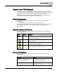
How to Use This Manual Related Documents How to Use This Manual This manual is for users of APOGEE® Automation Systems who use BACnet Field Panel Web Server to command and monitor their APOGEE field panels. It is designed to describe the functions and applications of BACnet Field Panel Web Server. To effectively use this manual, you must be familiar with the basic operation of the APOGEE Building Automation Systems and a Web browser.
How to Use This Manual Contact Us ⊳. Intermediate results (what will happen following the execution of a step), are designated with a ⇨. Results, which inform the user that a task was completed successfully, are designated with a ⇨. 1. Select Start > Programs > Siemens > GMS > Composer. ⇨The Project Management window displays. 2. Open an existing project or create a new one. ⇨The project window displays. Actions that should be performed are specified Type F for Field panels. in boldface font.
Chapter 1 - Introduction to BACnet Field Panel Web Server BACnet Field Panel Web Server Overview Chapter 1 - Introduction to BACnet Field Panel Web Server Chapter 1 discusses the following topics: ● BACnet Field Panel Web Server Overview [➙ 9] ● Compatibility [➙ 10] ● Applications [➙ 10] BACnet Field Panel Web Server Overview BACnet Field Panel Web Server User Interface (Web Server or FPWeb UI) includes all the applications a facility operator needs to easily configure, monitor, and control the APOGEE® Au
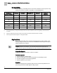
Chapter 1 - Introduction to BACnet Field Panel Web Server Compatibility Compatibility See the following compatibility chart for the minimum firmware revision required to fully support each revision of FINlite, the FPWeb UI, and APOGEE Editor. BACnet Field Panel Web Server Firmware Revisiona) FINlite Revision UI/Launch Pad Revisionb) FPWeb UI for Desigo® CC™ APOGEE Editor Revisionc) FIN Builder Revision/ Connector 3.5 1.5.14 1.5.14 1.5.14 1.0.0.17 3.0.235/1.5.6 3.4 1.4.39 1.4.39 1.4.39 1.0.
Chapter 1 - Introduction to BACnet Field Panel Web Server Applications Reports ● ● ● Displays a Point Log Report for the points which meet the selected criteria. Displays a Totalized Point Report for the points which are totalized. Generates a printer-ready format of the Point Log Report or the Totalized Point Report. Trending ● ● ● Displays Trend data in graphical or report format. Allows the ability to view Trend Log Object data or dynamic trend data by polling point objects.
Chapter 1 - Introduction to BACnet Field Panel Web Server Applications Change Panel Time Allows you to modify panel time. FLN Device Editor Allows you to create, modify, delete, and discover FLN Devices on multiple FLN types. Initial Value Editor Allows you to set and modify initial values. Database Manager Allows you to backup and restore ALN databases, and backup, restore, and replicate programmable FLN device databases. User Account Editor Allows you to create, modify, and delete user accounts.
Chapter 2 - BACnet Field Panel Web Server System Administration Prerequisites and Browser Requirements for BACnet Field Panel Web Server Chapter 2 - BACnet Field Panel Web Server System Administration Chapter 2 discusses the following topics: ● Prerequisites and Browser Requirements for BACnet Field Panel Web Server [➙ 13] ● Prerequisites for FINlite Graphics Tool [➙ 14] ● Enabling or Disabling Web Server [➙ 15] ● Loading the User Interface [➙ 16] ● Performance and Limitations [➙ 18] ● Network Configuratio
Chapter 2 - BACnet Field Panel Web Server System Administration Prerequisites for FINlite Graphics Tool NOTE: If you use Internet Explorer, do not select the Compatibility View options located in the IE Tools menu. ● ● Cookies must be enabled. This can be done by selecting Options from the Tools menu in most browsers. Adobe Flash Player Plug-in Version 25.0.0.x or later. The user interface may prompt you to update if an older version of Adobe Flash Player is installed.
Chapter 2 - BACnet Field Panel Web Server System Administration Enabling or Disabling Web Server Enabling or Disabling Web Server Be sure that the FPWeb license (LSM-FPWEB) is installed on the field panel that will be accessed by FINlite graphics.
Chapter 2 - BACnet Field Panel Web Server System Administration Loading the User Interface Loading the User Interface Loading or Upgrading the User Interface Using the Siemens Launch Pad Complete this procedure to load or upgrade the User Interface file when using the Siemens Launch Pad (recommended method). 1. From the Tools menu in the Siemens Launch Pad tool, select Deploy Web Server To Panel. The Deployment dialog box displays the version of the user interface you are about to install. 2.
Chapter 2 - BACnet Field Panel Web Server System Administration Loading the User Interface 3. At the HMI prompt, type S, H, E, W, U (System, Hardware, Ethernet, Webserver, Uiupgrade). 4. When prompted, type Y (Yes) and press ENTER. The User Interface and support files will be installed from the USB memory device in the field panel’s Drive B to the field panel’s internal flash drive (IFD) and to the field panel’s Drive A.
Chapter 2 - BACnet Field Panel Web Server System Administration Performance and Limitations Performance and Limitations ● ● ● ● ● ● An interface is available via the Human-Machine Interface (HMI) to save files to and restore files from the RAM drive, USB media, or the Field Panel’s Internal Flash Drive (IFD). For more information, see the APOGEE BACnet ALN Field Panel User's Manual (125-3020).
Chapter 2 - BACnet Field Panel Web Server System Administration Performance and Limitations ● ● Lexar Media JumpDrive Secure USB 2.0 512 MB flash disk MARKEM 1 GB USB Memory Stick Memorex 2 GB flash disk 1 GB TravelDrive™ USB Flash Drive 2 GB TravelDrive™ USB Flash Drive NCP XDrivePlus MMC/SD reader Newman USB 1.1 64 MB flash disk PNY Attache USB 1.1 64 MB flash disk Attache (U3) 1 GB Attache 2 GB Attache 8 GB 1 GB Attache USB Flash Drive PQI MMC/SD reader RedLeaf USB 2.
Chapter 2 - BACnet Field Panel Web Server System Administration Network Configuration - IP Address Tips to Improve Performance of BACnet Field Panel Web Server Allow Browser Caching of Adobe Flash Player This setting will be particularly helpful once the panel database is stable. This allows the BACnet Field Panel Web Server to keep information about the panel database without needing to continuously read it from the panel. 1. Right click while in a browser and accessing the BACnet Field Panel Web Server.
Chapter 2 - BACnet Field Panel Web Server System Administration Network Configuration - IP Address Network Configuration - IP Address It is strongly recommended that the BACnet Field Panel Web Server is configured with a private IP address on a VLAN, rather than a public (Internet) IP address. If the BACnet Field Panel Web Server is configured with a public address, there is a potential security risk to the system integrity from unauthorized access.
Chapter 2 - BACnet Field Panel Web Server System Administration Language Support Language Support Dynamic text refers to text that lists object names, descriptors, state text, and other information that you can define. Static text refers to text in the user interfaces (Web Server user interface, and FINlite Graphics Tool), such as menu titles, labels, error messages, and other information that you cannot modify.
Chapter 3 - User Interface Navigation Login Page Chapter 3 - User Interface Navigation Chapter 3 discusses the following topics: ● Login Page [➙ 23] – Configuring the Login Page Graphic [➙ 26] ● User Interface after Logon [➙ 27] – Navigation Pane User Interface [➙ 28] – Device/Points Bar Icons and Messages [➙ 30] – Application Area User Interface [➙ 32] – Device/Points Navigation Tree [➙ 33] ● Common Editor Fields and Buttons [➙ 34] Login Page If you have problems connecting to the BACnet Field Panel Web
Chapter 3 - User Interface Navigation Login Page Accessing the Login Page through a Web Browser 1. Open a supported Web browser on the computer. 2. Type one of the following in the Address field: – IP address of the field panel. – Field panel node name/Fully Qualified Domain Name. NOTE: The browser must be configured to ignore the proxy settings for the panel names and/or IP addresses. See Chapter 14 - Troubleshooting for more information. ⇨ The End User License Agreement (EULA) page displays. 3.
Chapter 3 - User Interface Navigation Login Page Accessing the Login Page through Launch Pad 1. Start Launch Pad. The End User License Agreement (EULA) page displays. 2. Click Accept to accept the End User License Agreement. 3. Click the Field Panel Web Server button. The login page displays with an additional Hostname/IP field that must be entered. 4.
Chapter 3 - User Interface Navigation Login Page Configuring the Login Page Graphic BACnet Field Panel Web Server provides a Login Page image, which you can change. To change the image on the Login Page: 1. Create a custom image file that is 398 × 263 pixels. 2. Name the file login.png. 3. Save the file to a USB drive. 4. Do one of the following to save this file in the field panel: – Using the USB drive as Drive B of the field panel, copy the login file to A:/wsroot/login.png.
Chapter 3 - User Interface Navigation User Interface after Logon User Interface after Logon Once you are logged in, the BACnet Field Panel Web Server user interface is divided into the status bar (1), the navigation pane (7), and the application area (8). 1 Status bar. 2 Alarms, Unack, Faults, Out Of Service, and Device Failures buttons indicate a count for the number of items in that status. These buttons can be clicked to generate a detailed report for each item in that status.
Chapter 3 - User Interface Navigation User Interface after Logon Navigation Pane User Interface The navigation pane includes seven main application bars for accessing the available applications. For descriptions of icons used in the Navigation Pane, see the Device/Points Bar Icons and Messages [➙ 30] section. For information about panel accessibility, see the Inaccessible Panels on the ALN [➙ 29] section. For more information on each application see the specific section in this manual.
Chapter 3 - User Interface Navigation User Interface after Logon 5 Scheduling: This application bar provides a tree view of panels and their associated Schedule, Command, and Calendar objects. Clicking a specific Schedule object in this tree view launches the scheduler view application displaying the schedule data for the selected object. 6 Create/Edit: This application bar provides buttons to start the editing applications.
Chapter 3 - User Interface Navigation User Interface after Logon When a database discovery is needed, but the panel database file is being synchronized, a status table displays, indicating the database file synchronization status for each panel database that is being synchronized: When a panel database file has been synchronized, the table displays the updated panel status: When all panels listed are synchronized, the status table closes, a successful database discovery occurs, and any yellow triangle ic
Chapter 3 - User Interface Navigation User Interface after Logon ● Clicking the green arrows to the right of the device name . During a database discovery, status messages will display: Static Icons Static icons in the Device/Points bar indicate the various characteristics of the panel node. A static icon associated with a panel node is fixed for the Web session. Icon Description Indication Red shield icon with a horizontal white bar. FPWeb license is not installed for the panel.
Chapter 3 - User Interface Navigation User Interface after Logon Dynamic Icons Dynamic icons in the Device/Points bar indicate the various states of the panel node. A dynamic icon associated with a panel node is updated when a change to the state of the panel is detected. Icon Description Indication Yellow triangle icon with a red exclamation point displayed on an ALN device. Database File Synchronization. Field panel database file synchronization is in progress. A status message displays.
Chapter 3 - User Interface Navigation User Interface after Logon Device/Points Navigation Tree When you click the Device/Points application bar, a navigation tree displays that includes a search box and a list of panels. Search Box The Device/Points search box allows searching for points by name. Type any part of the desired point name into the search box and a list of matching point names will display. Click the desired point name to access the point.
Chapter 3 - User Interface Navigation Common Editor Fields and Buttons Common Editor Fields and Buttons Many of the editors have common fields and buttons. Some fields represent common properties of BACnet objects including Object Identifier, Object Name, and Object Description.
Chapter 3 - User Interface Navigation Common Editor Fields and Buttons For instance, if you want to create a Binary Value object with an instance of 100, you would enter the following in the Point Editor Object Identifier: Upon successful creation of this object, the Object Identifier field will show both components: The Object Identifier field cannot be modified after creation. Object Reference Some BACnet objects have properties that reference other BACnet objects.
Chapter 3 - User Interface Navigation Common Editor Fields and Buttons Common Editor Buttons and Functions Each editor is set up similarly and uses common buttons: ● The plus ● The minus ● The Revert button restores all fields to the last saved values (this does not simply undo the last action). The Save button saves the object. The X button closes the application (without saving).
Chapter 4 - Status Bar Status Bar Counts and Reports Chapter 4 - Status Bar Figure 1: BACnet Field Panel Web Server Status Bar.
Chapter 4 - Status Bar Setup Exporting and Saving an Alarm Report The Alarm report can be exported to the system printer with a preview, or exported as a comma separated values (CSV) file and saved. 1. To export the Alarm report, click the Export to CSV button in the Alarm Report pane. 2. In the dialog box that opens, browse to the desired location to save the CSV file. Printing an Alarm Report 1. To print the Alarm report, click the Print button in the Alarm Report pane. 2.
Chapter 4 - Status Bar Setup 1. Click the Setup button on the Status Bar. The Setup window displays. 2. Change the font size by using the UP and DOWN arrows in the Font Size field. 3. When accessing Web Server through a browser: Change the text language by using the Language drop-down menu. When accessing Web Server through the Siemens Launch Pad: Although this Language drop-down menu is active, the language must be changed using the Language drop-down within the Siemens Launch Pad.
Chapter 4 - Status Bar Logoff Logoff You can end a BACnet Field Panel Web Server session by manually logging off or by allowing the system to automatically log off. ● Manually logging off immediately prevents unauthorized users from accessing to the system and reduces network traffic. ● Automatic logoff ends a BACnet Field Panel Web Server session after a period of inactivity at the browser. For more information, see the User Interface Description for the User Account Editor section.
Chapter 5 - Point Commander Application Point Commander Application Overview Chapter 5 - Point Commander Application Chapter 5 discusses the following topics: ● Point Commander Application Overview [➙ 41] – User Interface Description for the Point Commander Application [➙ 42] – Tips for Using the Point Commander Application [➙ 46] ● Using the Point Commander Application [➙ 47] – Commanding Point Values [➙ 47] – Disabling and Re-enabling a Point (Out of Service) [➙ 48] – Resetting the Totalized Value [➙ 49]
Chapter 5 - Point Commander Application Point Commander Application Overview The BACnet Field Panel Web Server Point Commander Application allows you to manually control a point and override the pre-established automatic controls in a PPCL program or the Scheduler application. Under normal operating conditions, allow the APOGEE® Automation System to control the building through programs such as PPCL, rather than relying on manual control.
Chapter 5 - Point Commander Application Point Commander Application Overview 1 Point Name and Description ● The Object Name field shows the point name. ● (Optional) The Description field displays additional point information. ● The point name, point type, data type, and instance ID displays in the header of the Commanding window. 2 To close the Commander window, click the X in the top right corner of the window.
Chapter 5 - Point Commander Application Point Commander Application Overview 4 Status Indicators The following status indicators, indicate status with a check mark: ● The In-Alarm check box indicates when the point is in an alarm status. See the Status Bar section for more information. ● The Fault check box indicates when the point is in a fault status. ● The Overridden check box indicates when the point has been manually overridden.
Chapter 5 - Point Commander Application Point Commander Application Overview 1 Priority array for the point. 2 The Relinquish Default field displays the default value of the point. This value is assigned to the present value when all priorities (1 through 16) are relinquished. 3 The Present Value field shows the present value of the point at the current highest priority, and allows you to change that value. 4 The Priority drop-down menu shows the current priority, and allows you to change the priority.
Chapter 5 - Point Commander Application Point Commander Application Overview Figure 3: Example of OTHER Error Feedback Message. Tips for Using the Point Commander Application ● ● ● ● Points can be commanded from the Navigation pane or from an animated graphic. See the FINlite Graphics Tool [➙ 220] section for information on commanding a point from a graphic. You can only command points if you have been given Command or higher access level to the point.
Chapter 5 - Point Commander Application Using the Point Commander Application Using the Point Commander Application The following procedures are outlined in this section: ● Commanding Point Values [➙ 47] ● Disabling and Re-enabling a Point (Out-of-Service) [➙ 48] ● Resetting the Totalized Value [➙ 49] ● Priority Arrays [➙ 49] – Changing Point Priority (Basic Commanding Window) [➙ 49] – Changing Point Priority (Advanced Commanding Window) [➙ 50] Commanding Point Values Commanding a point means using the Po
Chapter 5 - Point Commander Application Using the Point Commander Application CAUTION Release All Commanded Points Remember to eventually release all commanded points to NULL priority so that the system is automatically controlled. In the Current Value field on the Basic or Advanced Commander window, type N. NULL will be auto-filled into the field. Failure to release commanded points may lead to unexpected results.
Chapter 5 - Point Commander Application Using the Point Commander Application Resetting the Totalized Value The totalized value can be reset to any valid value for the selected point type. To reset the totalized value: 1. Access the Commanding window through the Devices/Points bar in the navigation pane on the left side of the screen. 2. Drill down to the desired point. 3.
Chapter 5 - Point Commander Application Using the Point Commander Application Changing Point Priority (Advanced Commanding Window) In the advanced Commanding window, the point priority can be changed in the Priority drop-down field. The value of the point can be changed in the current highest priority field. 1. Click the drop-down arrow in the Priority field to choose the priority. 2.
Chapter 6 - Graphics View 1 Tips for Using the Graphics View Chapter 6 - Graphics View Chapter 6 discusses the following topics: ● Tips for Using the Graphics View [➙ 51] ● Using the Graphics View [➙ 51] – Opening a Graphics View Tab [➙ 51] – Graphics Features [➙ 51] – Graphics File Types [➙ 52] – Graphics File Navigation [➙ 52] Tips for Using the Graphics View ● ● Graphics files can be viewed but not modified using the Graphics View in the BACnet Field Panel Web Server User Interface.
1 Chapter 6 - Graphics View Using the Graphics View Graphics File Types There are two types of graphics files. ● A standard graphic is one where any Point Values shown on the graphic comes from a specific device and a specific object. ● A Device Template Graphic is one where the Point Values shown on the graphic may come from a selected FLN device. Graphics File Navigation Graphics can be viewed through the Graphics application in the BACnet Field Panel Web (FPWeb UI) Server user interface.
Chapter 6 - Graphics View 1 Using the Graphics View Graphics can also be viewed using the Device/Points bar: 1. Select the Device/Points bar from the navigation pane on the left side of the FPWeb UI screen. All available panels will display. 2. Select the desired panel. If there are graphics files in the selected panel, the Graphics option will display underneath the panel name. 3. View the desired graphic by clicking the Graphics option and then the graphic name.
Chapter 7 - Reporting Point Log Report Application Chapter 7 - Reporting Chapter 7 discusses the following topics: ● Point Log Report Application [➙ 54] – User Interface Description for the Point Log Report Application [➙ 54] – Running a Point Log Report [➙ 55] ● Totalized Point Report Application [➙ 58] – User Interface Description for the Totalized Point Report Application [➙ 58] – Using the Totalized Point Report Application [➙ 59] Point Log Report Application The Point Log Report application allows yo
Chapter 7 - Reporting Point Log Report Application ● ● ● ● ● ● ● ● ● The Panels drop-down allows you to choose the panel(s) within which to run the Point Log report. The Name field allows you to search on the point name, using wildcard characters if necessary. The Type drop-down allows you to choose the type of point on which to run the Point Log Report. The Search BACnet FLN check box determines whether or not the report will include MS/TP points. The Go button runs the report.
Chapter 7 - Reporting Point Log Report Application NOTE: A Point Log report can be run on multiple field panels at the same time. In the Panels drop-down field, select all of the desired panels, or choose All. The selected panels are indicated by checkmarks. (Tip: To select all but one or a few panels, click All and then deselect the unwanted panels.) Querying and Filtering a Point Log Report Point Log reports can be queried on the point name and point type.
Chapter 7 - Reporting Point Log Report Application Generating a Point Log Report To generate a Point Log report, click Go. The Point Log report results display as a table in the report pane. To cancel a report in progress, click Cancel. Changing the Width and Order of the Report Columns The width and order of the report table columns can be changed in the report pane. The report information can also be sorted by column.
Chapter 7 - Reporting Totalized Point Report Application Printing the Point Log Report 1. Click the Print button A print dialog box opens. at the top right section of the report pane. 2. Choose the desired printer and click OK. 3. To close the Point Log report, click the on the title tab of the report pane.
Chapter 7 - Reporting Totalized Point Report Application ● The Export to CSV button allows you to export the report data to a comma separated values file which can be saved. Using the Totalized Point Report Application Running a Totalized Point Report NOTE: A Totalized Point report can be run on multiple panels at the same time. In the Panels drop-down field, select all of the desired panels, or choose All. When a panel is selected, a checkmark displays in front of the panel name.
Chapter 7 - Reporting Totalized Point Report Application Changing the Width and Order of the Report Columns The width and order of the report table columns can be changed in the report pane. The report information can also be sorted by column. ● To change the width of the columns, click and hold the vertical edge of the column header and move the line to the desired width. ● To change the order of the columns, click and hold the column and move it to the desired location within the table.
Chapter 8 - Trend View 2 Trend View Overview Chapter 8 - Trend View Chapter 8 discusses the following topics: ● Trend View Overview [➙ 61] – Tips for Using the Trend Application [➙ 61] ● Using the Trend Application [➙ 61] – Viewing Trend Data of a Single Trended Point [➙ 61] – Viewing Trend Data of Multiple Trended Points [➙ 63] – Printing a Trend Graph [➙ 65] – Customizing a Trend Graph [➙ 66] Trend View Overview A Trend View application tab can be opened for a particular Trend Log Object from the Devi
2 Chapter 8 - Trend View Using the Trend Application 3. OR 4. Click the Device/Points bar in the navigation pane. 5. Choose the desired panel. 6. Click the Trends option to see the Trend Object list in that panel. 7. THEN 8. Select a Trend Object from either list in the navigation pane by double-clicking on the Trend Object name. A trend graph displays in the right pane with the trend data of the selected Trend Object. 62 Siemens Industry, Inc.
Chapter 8 - Trend View Using the Trend Application 2 You can navigate to other applications while the system is generating a Trend graph. ● To cancel a Trend graph, do one of the following: – Start a new Trend graph – Close the trend viewing tab – Log off BACnet Field Panel Web Server. For more information, see the Customizing a Trend Graph [➙ 66] section.
2 Chapter 8 - Trend View Using the Trend Application 64 Siemens Industry, Inc.
Chapter 8 - Trend View 2 Using the Trend Application Printing a Trend Graph NOTE: Do not use the browser print feature for printing BACnet Field Panel Web Server reports or graphs. 1. Once the Trend graph is generated, click the Print button in the upper right corner of the trending pane. The system generates a printer-ready format of the graph and opens the Print dialog box. 2. Choose the desired printer and click OK. 3. To close the Trend graph, click the on the title tab of the trending pane.
2 Chapter 8 - Trend View Using the Trend Application 5. To close the Trend graph, click the on the title tab of the trending pane. Customizing a Trend Graph Trend graphs can be customized within BACnet Field Panel Web Server. Customization options include: ● Vertical access values ● Dynamic display ● Viewing more data ● Line color and thickness ● Fill alpha ● Chart type Vertical Access Values To change the values of the vertical access, use the numeric scroll box to choose values.
Chapter 8 - Trend View 2 Using the Trend Application The trend graph will now add the previous 50 data samples to the display. Clicking the button again adds another 50 data samples to the display. Line Color and Thickness, Fill Color, and Chart Type The line color, line thickness, fill color (“Fill Alpha”), and chart type (lines, columns, or steps) can be customized using the dialog box which displays at the bottom of the right pane.
2 Chapter 8 - Trend View Using the Trend Application Trend Data Upload Trend Data Upload is a feature with Firmware Revision 3.5 or later that allows you to configure automatic export of Trend data to a user-defined network location using File Transfer Protocol (FTP). A FTP Server is necessary to be configured for uploading trend data collected by the field panel. Individual Trend Objects may be enabled for FTP Upload. A FTP Server is not necessary if the FTP Upload feature is not used.
Chapter 8 - Trend View 2 Using the Trend Application Troubleshooting FTP Upload NOTE: The FTP Upload feature will not upload a file to the FTP Server until the notification threshold is reached. By default, this occurs when the number of samples has reached 80% of the maximum sample storage. If Trend samples are not getting uploaded, use the following procedure to troubleshoot. Use a computer with an FTP Client installed or use the Command Prompt to access the FTP Server. 1.
3 Chapter 9 - Schedule View Scheduler Application Overview Chapter 9 - Schedule View Chapter 9 discusses the following topics: ● Scheduler Application Overview [➙ 70] – User Interface Description for the Scheduler Application [➙ 70] – Tips for Using the Scheduler Application [➙ 72] ● Using the Scheduler Application [➙ 73] Scheduler Application Overview The BACnet Field Panel Web Server Scheduler Application allows you to view existing schedules, referenced objects, and schedule details.
Chapter 9 - Schedule View Scheduler Application Overview ● ● ● ● ● ● ● ● ● ● 3 The Objects section of the Schedule window displays the objects associated with the schedule being viewed. The left and right arrows at the top of the Schedule window allow you to view a prior or future day, work week, week, or month, depending on which mode you are viewing. The up and down arrows allow you to view the next or previous year. The Today button displays the schedules for the current day.
3 Chapter 9 - Schedule View Scheduler Application Overview Tips for Using the Scheduler Application ● ● Schedule details can be viewed using Today, Day, Work Week, Week, or Month views. Use the buttons at the top of the Schedule window to choose among the available views or to advance to the next Schedule segment (day, work week, week, or month).
Chapter 9 - Schedule View 3 Using the Scheduler Application Using the Scheduler Application 1. Select the Scheduling bar from the navigation pane on the left side of the BACnet Field Panel Web Server screen. All available panels will display. 2. Select the desired panel and schedule object by clicking the panel name and then the schedule object name. NOTE: Command objects and calendar objects cannot be opened through the Scheduler application.
Chapter 10 - Create/Edit Trend Application Chapter 10 - Create/Edit Chapter 10 discusses the following topics: ● Trend Application [➙ 74] ● Point Editor Application [➙ 78] ● Schedule/Command/Calendar Object Editors [➙ 97] ● Event Enrollment [➙ 112] ● Notification Class [➙ 115] ● Remote Notification [➙ 123] ● PPCL [➙ 129] Trend Application This section discusses the following topics: ● Trend Application Overview [➙ 74] – User Interface Description for the Trend Editor Application [➙ 74] – Off-Node Trending
Chapter 10 - Create/Edit Trend Application ● ● ● ● ● ● ● ● ● The Trend Object Editor window displays on the right side of the screen. The Object Name field allows you to name the Trend Object using up to 30 characters. This field is mandatory for creating a Trend Object and cannot be edited in an existing Trend Object. The Object Identifier field displays the Trend Object identification information. If you do not enter a value, the controller will automatically enter the next available Object ID.
Chapter 10 - Create/Edit Trend Application ● The Start Date/Time fields allow you to specify a date/time value for a trend to begin (if the enable check box is checked). These fields can be edited in existing Trend Objects. ● The End Date/Time fields allow you to specify a date/time value for a trend to end (if the enable check box is checked). These fields can be edited in existing Trend Objects. ● The Stop when full check box allows you to define whether trending will stop when the trend log is full.
Chapter 10 - Create/Edit Trend Application Using the Trend Editor Application Creating a Trend Object 1. Select the Trend icon from the Create/Edit bar. The Trend Editor window will open. 2. Click Select a Panel at the top of the left pane of the Trend Editor window to display available panels. 3. Select the desired panel by clicking the panel name in the left pane of the Trend Editor window. 4. Click the + button at the bottom left of the Trend Editor window.
Chapter 10 - Create/Edit Point Editor Application Deleting a Trend Object 1. Select the Trend icon from the Create/Edit bar. The Trend Editor window will open. 2. Click Select a Panel at the top of the left pane of the Trend Editor window to display available panels. 3. Select the desired panel and the desired Trend Object by clicking the panel name and then the Trend Object name. The Trend Object information window displays Trend Object details. 4.
Chapter 10 - Create/Edit Point Editor Application User Interface Description for the Point Editor Application The Point Editor application can be accessed by clicking the Point icon in the Create/Edit bar in the navigation pane on the left side of the Web Server screen: NOTE: Programmable BACnet MS/TP FLN devices residing on a field panel’s local MS/TP FLN ports are accessible through this editor. Routed MS/TP FLN and BACnet IP FLN devices are not accessible. 79 Siemens Industry, Inc.
Chapter 10 - Create/Edit Point Editor Application The Point Editor navigation pane displays on the left side of the editor. Panels, P1 FLN devices, Integration FLN devices, and MS/TP FLN programmable devices display in the Point Editor’s device tree. When you select a panel or device, the points in that panel or device display in the object list in the bottom half of the tree: 80 Siemens Industry, Inc.
Chapter 10 - Create/Edit Point Editor Application When you select a point from the object list for an ALN panel device, or P1 device, or UEC/PANEL device, the point characteristic information displays in the right pane of the editor. Not all parameters are shown in the following images: 81 Siemens Industry, Inc.
Chapter 10 - Create/Edit Point Editor Application ● ● ● ● ● The Point Editor window displays on the right side of the screen. The Object Name field allows you to name the point using up to 30 characters. This field is required for the creation of a point and cannot be edited. The Object Identifier field displays the point Object Identifier information. An Object Identifier consists of an object type and instance number.
Chapter 10 - Create/Edit Point Editor Application User Interface Description for the PTEC Point Editor When you select a PTEC device, the object list indicates the ability to select the Custom Point Table: After selecting the Custom Point Table from the object list, the PTEC Point Editor table display the custom application point objects: ● The Name column displays the point name (maximum of 12 characters: uppercase letters A through Z, numbers 0 through 9, period, question mark, character space).
Chapter 10 - Create/Edit Point Editor Application ● ● ● The Type column displays in a drop-down the point type (AO or BO). The Instance # column displays the instance number (1,000 or higher). The Engineering Units column displays, in a drop-down, the standard BACnet engineering units used to indicate point value. This column is disabled for BO points. ● The State Text Table column displays, in a drop-down, the state text used to indicate point value. This column is disabled for AO points.
Chapter 10 - Create/Edit Point Editor Application – – – – – – – – – – – Pneumatic Thermistor 10K Type 2 Thermistor 10K Type 3 Thermistor 100K L Type RTD 1K Platinum 375 RTD 1K Platinum 385 RTD 1K @ 32F Nickel LG-Ni RTD 1K @ 70F Nickel JCI RTD 1K Nickel DIN Custom If you are not sure what values to enter for the slope and intercept, the Point Editor supports a Slope/Intercept Calculator for Modular and Compact field panels and UEC/Panel on FLNs.
Chapter 10 - Create/Edit Point Editor Application ● ● ● ● ● ● ● ● ● ● ● – Voltage – Current – Thermistor 10K Type 2 – Thermistor 10K Type 3 – Thermistor 100K – RTD 1K Platinum 375 – RTD 1K Platinum 385 – RTD 1K @ 32F Nickel LG-Ni – RTD 1K @ 70F Nickel JCI – RTD 1K Nickel DIN The Calculation Units radio buttons (LAI points only) allow you to choose from English or S.I. The Slope field displays the calculated slope of the point. The Intercept field displays the calculated intercept of the point.
Chapter 10 - Create/Edit Point Editor Application Using the Point Editor Application Creating a Point for Panel on ALN or UEC/PANEL on FLN CAUTION All point names on ALN level devices must be unique. Do not create two or more points with the same name in two or more different panels, especially if that point name is to be referenced in PPCL. To verify that a point name has not been used, run a Point Log Report. See the Point Log Report section for more information. 1.
Chapter 10 - Create/Edit Point Editor Application The Save button is unavailable once the modifications are complete. NOTE: After creating custom points on a UEC/PANEL on FLN device, be sure to update the FLN custom application using the Database Manager. Using the Slope/Intercept Calculator 1. Click the Slope/Intercept Calculator button. The Slope/Intercept Calculator window opens. 2. Select the Sensor Type or Actuator Type being created. 3.
Chapter 10 - Create/Edit Point Editor Application Creating a PTEC Point 1. Select the Point icon from the Create/Edit bar. The Point Editor window will open. 2. If available panels/devices do not display, click Select a Device at the top of the left pane of the Point Editor window to display available panels/devices. 3.
Chapter 10 - Create/Edit Point Editor Application Intrinsic Alarming on ALN Panel Intrinsic reporting allows a device to provide one or more event sources, intrinsic to the device, which generate alarm or event notifications that may be directed to one or more destinations. For more information on Intrinsic Alarming, see the APOGEE BACnet ALN Field Panel User's Manual (125-3020). An Intrinsic Alarm can be created using the Point Editor application.
Chapter 10 - Create/Edit Point Editor Application Viewing a Point 1. Click the Point icon from the Create/Edit bar. The Point Editor window opens. 2. If available panels/devices do not display, click Select a Device at the top of the left pane of the Point Editor window to display available panels/devices. 3. Select the desired panel/device and the desired point by clicking the arrow next to the panel name to display devices, and then clicking the device name in the left pane of the Point Editor window.
Chapter 10 - Create/Edit Point Editor Application 3. To select the desired PTEC device, click the arrows next to the supervising panel name and next to its FLN name, and then click the PTEC device name in the left pane of the Point Editor window. When you select a PTEC device, the object list indicates the ability to select the Custom Point Table. Select the Custom Point Table object. The PTEC Point Editor table displays all custom points (user-defined BACnet objects) in the PTEC device.
Chapter 10 - Create/Edit Point Editor Application Modifying a PTEC Point 1. Select the Point icon from the Create/Edit bar. The Point Editor window will open. 2. If available panels/devices do not display, click Select a Device at the top of the left pane of the Point Editor window to display available panels/devices. 3.
Chapter 10 - Create/Edit Point Editor Application Configuring a Point for Totalization The totalization function accumulates the runtime value of a point. It can be used to: ● Accumulate run time for fans and pumps. ● Accumulate volume total from a flow rate sensor. ● Calculate degree days (used in PPCL). To configure a point for totalization: 1. Select the Point icon from the Create/Edit bar. The Point Editor window opens. 2.
Chapter 10 - Create/Edit Point Editor Application 5. Click the - button at the bottom left of the Point Editor window. A message box displays, allowing you to verify deletion of the selected point(s). Click Yes to delete the selected point(s). NOTE: After modifying custom points on a UEC/PANEL on FLN device, be sure to update the FLN custom application using the Database Manager. 95 Siemens Industry, Inc.
Chapter 10 - Create/Edit Point Editor Application Deleting a PTEC Point 1. Click the Point icon from the Create/Edit bar. The Point Editor window opens. 2. If available panels/devices do not display, click Select a Device at the top of the left pane of the Point Editor window to display available panels/devices. 3.
Chapter 10 - Create/Edit Schedule/Command/Calendar Object Editors Schedule/Command/Calendar Object Editors This section discusses the following topics: ● Schedule/Command/Calendar Object Editors Overview [➙ 97] – User Interface Description for the Schedule/Command/Calendar Object Editors [➙ 98] – Tips for Using the Schedule/Command/Calendar Object Editors [➙ 102] ● Using the Schedule Object Editor [➙ 102] – Creating a Schedule Object [➙ 102] – Viewing a Schedule Object [➙ 106] – Modifying a Schedule Object
Chapter 10 - Create/Edit Schedule/Command/Calendar Object Editors The following attributes of an existing Calendar Object can be modified through the Calendar Editor: ● Description ● Date List You can also create Command Objects to be used with the Schedule Editor. The Command Object created will be referenced by the Schedule Object. You can also view, delete, and modify existing Command Objects.
Chapter 10 - Create/Edit Schedule/Command/Calendar Object Editors ● The Object Name field allows you to name the Schedule Object using up to 30 characters. This field is required for creating a schedule and cannot be edited in existing schedules. ● The Object Identifier field displays the Object identification information. If you do not enter a value, the controller will automatically enter the next available Object ID. This field cannot be edited in existing schedules.
Chapter 10 - Create/Edit Schedule/Command/Calendar Object Editors The Command Object Editor window displays: ● ● ● ● ● ● ● The ? button displays the Command Object Editor Help window. The Object Name field allows you to name the Command Object using up to 30 characters. This field is required when creating a Command Object and cannot be edited in existing schedules. The Object Identifier field displays the Object identification information.
Chapter 10 - Create/Edit Schedule/Command/Calendar Object Editors Calendar Object Editor User Interface The Calendar Object Editor window can be accessed using the Create/Edit bar in the navigation pane on the left side of the screen. Move your cursor over the Schedule icon to view the Calendar icon. Click the Calendar icon to open the Calendar Object Editor window: The Calendar Object Editor window displays: 101 Siemens Industry, Inc.
Chapter 10 - Create/Edit Schedule/Command/Calendar Object Editors ● ● ● ● The Object Name field allows you to name the Calendar Object using up to 30 characters. This field cannot be edited in existing schedules. The Object Identifier field displays the Object identification information. If you do not enter a value, the controller will automatically enter the next available Object ID. This field cannot be edited in existing schedules.
Chapter 10 - Create/Edit Schedule/Command/Calendar Object Editors The Save button is not available once the modifications are complete. Creating a Weekly Schedule 1. From within the Object Editor window, click the Weekly Schedule button to open the Edit Weekly Schedule window. 2. Choose the day of the week by clicking the tabs at the top of the window. 3. Click the + sign at the bottom left of the window to add rows to the Time/Values table. 4.
Chapter 10 - Create/Edit Schedule/Command/Calendar Object Editors Creating a Schedule Exception 1. From within the Object Editor window, click the Exception Schedule button to open the Edit Exception Calendar window. 2. Click the + sign at the bottom left of the window to add an Exception Schedule. – Choose Date, Date Range, Week’N’Day, or Reference (to reference an existing Calendar Object) – Enter schedule details. 3. Click the Edit Time Values button to add time values to the Exception Schedule.
Chapter 10 - Create/Edit Schedule/Command/Calendar Object Editors 4. Click the value under the Priority column to change the exception priority. The Exception priority is the priority in which exception schedules are executed. If there are more than one exception schedules for the same time, the exception schedule with the higher priority will be executed. 5. Click the minus sign at the bottom left of the window to delete an Exception Schedule. Command Point Objects 1.
Chapter 10 - Create/Edit Schedule/Command/Calendar Object Editors 3. Click the minus sign at the bottom left of the window to delete a Command Object from the Schedule Object. Viewing a Schedule Object 1. Click the Schedule icon from the Create/Edit bar. The Schedule Editor window displays. 2. Click Select a Panel at the top of the left pane of the Schedule Editor window to display available panels. 3.
Chapter 10 - Create/Edit Schedule/Command/Calendar Object Editors Deleting a Schedule Object 1. Click the Schedule icon from the Create/Edit bar. The Schedule Editor window displays. 2. Click Select a Panel at the top of the left pane of the Schedule Editor window to display available panels. 3. Select the desired panel and the desired schedule by clicking the panel name and then the schedule object name. The Schedule Editor window displays the schedule object details. 4.
Chapter 10 - Create/Edit Schedule/Command/Calendar Object Editors Start/Stop Time Optimization (SSTO) When the Schedule Optimization Enabled check box is selected: ● The 12 default SSTO Action Titles are added to the Action list (see table below). ● The + and - buttons of the Action list are grayed out. ● You can add commands to the action. ● You cannot change the name of the actions. The Action Title field in the Actions dialog box is grayed out.
Chapter 10 - Create/Edit Schedule/Command/Calendar Object Editors The Command Object Editor window displays the command object details. Modifying a Command Object 1. Click the Command icon from the Create/Edit bar (hover over the Schedule icon to view it). The Command Object Editor window displays. 2. Click Select a Panel at the top of the left pane of the Command Object Editor window to display available panels. 3.
Chapter 10 - Create/Edit Schedule/Command/Calendar Object Editors Using the Calendar Object Editor Creating a Calendar Object 1. Click the Calendar icon from the Create/Edit bar (hover over the Schedule icon to view it). The Calendar Object Editor window displays. 2. Click Select a Panel at the top of the left pane of the Calendar Object Editor window to display available panels. 3. Select the desired panel by clicking the panel name in the left pane of the Calendar Object Editor window. 4.
Chapter 10 - Create/Edit Schedule/Command/Calendar Object Editors Viewing a Calendar Object 1. Click the Calendar icon from the Create/Edit bar (hover over the Schedule icon to view it). The Calendar Object Editor window displays. 2. Click Select a Panel at the top of the left pane of the Calendar Object Editor window to display available panels. 3. Select the desired panel and the desired calendar object by clicking the panel name and then the calendar object name.
Chapter 10 - Create/Edit Event Enrollment Event Enrollment For information about intrinsic alarming, see the Point Editor [➙ 78] section of this document. To receive alarms from BTECs and PPMs, Event Enrollment must be used.
Chapter 10 - Create/Edit Event Enrollment ● ● ● ● ● ● ● ● The Object Name field allows you to name the Event Enrollment Object using up to 30 characters. This field cannot be edited in an existing object. The Object Identifier field displays the point Object Identifier information. An Object Identifier consists of an object type and instance number. The object type is the BACnet standard object type enumeration value (Event Enrollment object type enumeration value is 9).
Chapter 10 - Create/Edit Event Enrollment ● The Notification Class drop-down menu allows you to choose the notification class that the Event Enrollment Object will use. If no Notification Class is specified, no panels will be notified. Type-specific Parameters: ● ● ● ● ● ● The States list displays the available alarm values. This parameter applies to COS Event Enrollment Object types only. The Feedback Point drop-down menu provides the object reference for the feedback from the object to be monitored.
Chapter 10 - Create/Edit Event Enrollment Viewing an Event Enrollment Object 1. Click the Event Enrollment icon from the Create/Edit bar. The Event Enrollment Editor window displays. 2. Click Select a Panel at the top of the left pane of the Event Enrollment Editor window to display available panels. 3. Select the desired panel and the desired Event Enrollment object by clicking the panel name and then the Event Enrollment object name.
Chapter 10 - Create/Edit Notification Class Notification Class Section Overview This section discusses the following topics: ● Notification Class Overview – User Interface Description for the Notification Class Editor ● Notification Class Editor Step-by-Step Instructions – Creating an Notification Class Object – Modifying an Notification Class Object – Viewing an Notification Class Object – Deleting an Notification Class Object User Interface Description for the Notification Class Editor The Notification
Chapter 10 - Create/Edit Notification Class ● ● ● ● ● The Object Name field allows you to name the Notification Class Object using up to 30 characters. This field is required for creating a Notification Class Object and cannot be edited in an existing object. The Object Identifier field displays the Object identification information. If you do not enter a value, the controller will automatically enter the next available Object ID. This field cannot be edited in an existing object.
Chapter 10 - Create/Edit Notification Class – Transitions – Defines which transitions are sent by the Notification Class (Off Normal, Fault, Normal). – Confirmed notification – Enables confirmed notification, which means that the notification expects an acknowledgement of receipt from the notification recipient. Not available if broadcasts are selected for notifications. ● (Optional) The Remote Destinations table is a table which lists remote recipient destinations and rules.
Chapter 10 - Create/Edit Notification Class Creating a Notification Class Object 1. Click the Notification Class icon from the Create/Edit bar. The Notification Class Editor window displays. 2. Click Select a Panel at the top of the left pane of the Notification Class Editor window to display available panels. 3. Select the desired panel by clicking the panel name in the left pane of the Notification Class Editor window. 4. Click the + button at the bottom left of the Notification Class Editor window.
Chapter 10 - Create/Edit Notification Class 120 Siemens Industry, Inc.
Chapter 10 - Create/Edit Notification Class Viewing a Notification Class Object 1. Click the Notification Class icon from the Create/Edit bar. The Notification Class Editor window displays. 2. Click Select a Panel at the top of the left pane of the Notification Class Editor window to display available panels. 3. Select the desired panel and the desired Notification Class object by clicking the panel name and then the Notification Class object name.
Chapter 10 - Create/Edit Notification Class Modifying a Notification Class Object 1. Click the Notification Class icon from the Create/Edit bar. The Notification Class Editor window displays. 2. Click Select a Panel at the top of the left pane of the Notification Class Editor window to display available panels. 3. Select the desired panel and the desired Notification Class object by clicking the panel name and then the Notification Class object name.
Chapter 10 - Create/Edit Remote Notification The Notification Class Editor window displays Notification Class object details. 4. Click the - button at the bottom left of the Notification Class Editor window. A message box will display, allowing you to verify deletion of the selected Notification Class object. Click Yes to delete the selected object.
Chapter 10 - Create/Edit Remote Notification Using the Remote Recipient List Editor The Remote Recipient List Editor can be accessed using the Create/Edit bar in the navigation pane on the left side of the screen. 1. Hover over the Notification Class icon to view the Remote Recipient List icon: 2. Click the Remote Recipient List icon to open the Remote Recipient List Editor window. 3. Choose the desired panel from the left navigation pane of the Remote Recipient List Editor window.
Chapter 10 - Create/Edit Remote Notification Creating a Remote Recipient 1. Click the + button at the bottom left of the Remote Recipient List Editor table. The Remote Recipient List displays a new Remote Recipient entry. The Remote Recipient List can contain up to 50 entries. The Index cell is populated with the next consecutive Index number available. This cell is not editable. The Alias cell is populated with the assigned Index number. The Alias cell is editable.
Chapter 10 - Create/Edit Remote Notification The Save button becomes grayed out once the modifications are complete. Deleting a Remote Recipient 1. Within the Remote Recipient List, click the Remote Recipient entry to be deleted. 2. Click the - button at the bottom left of the Remote Recipient List Editor window. The Remote Recipient line will be deleted from the Remote Recipient List. 3. Click Save. The Save button becomes grayed out once the modifications are complete.
Chapter 10 - Create/Edit Remote Notification Using the SMTP Configuration Editor You must communicate with the local Information Technology services to obtain the information necessary to update the SMTP Configuration fields. The SMTP Configuration Editor can be accessed using the Create/Edit bar in the navigation pane on the left side of the screen. 1. Move your cursor over the Notification Class icon to view the SMTP Configuration icon: 2.
Chapter 10 - Create/Edit Remote Notification ● ● ● ● ● ● The SMTP Server field displays the name or the IP address of the SMTP server which the field panel will use to send out remote notifications. You can edit this field if SMTP is enabled at the field panel. If you are using the SMTP server name, the panel must have a DNS server defined in order to resolve the SMTP server name. The Port field displays the port being used by the SMTP server (typically port 25).
Chapter 10 - Create/Edit PPCL The Remote Addresses chosen in the Remote Destinations table will receive a periodic e-mail notification to verify that the remote notification e-mail system is still functioning.
Chapter 10 - Create/Edit PPCL User Interface Description for the PPCL Editor The PPCL Editor window can be accessed using the Create/Edit bar in the navigation pane on the left side of the Web Server screen. The PPCL Editor navigation pane displays on the left side of the editor.
Chapter 10 - Create/Edit PPCL The rest of the PPCL Editor window consists of the Referenced Points list, the Commands list, the program pane, and the error table: 131 Siemens Industry, Inc.
Chapter 10 - Create/Edit PPCL The following fields and buttons are used in the PPCL Editor window. If you do not have access to a function, the field or button display is dimmed. ● The Device Tree allows you to choose the desired programmable device and PPCL program. ● The search box allows you to enter a search string. Matching words or character strings in the program code will be highlighted in the editing space. ● The Priority field allows you to view the priority of the PPCL program.
Chapter 10 - Create/Edit PPCL ● The Find/Replace button allows you to find a specific word or sequence of characters in the program and replace it with another specific word or sequence of characters. ● The Settings button allows you to customize the settings in the PPCL Editor and the PPCL Assist feature. See the PPCL Assist section for more information. The Update button (PTEC and UEC devices) opens the Database Manager.
Chapter 10 - Create/Edit PPCL NOTE: If a point is not present in the Device/Points list, it will not appear in the Referenced Points list. The default setting for the Data Refresh Rate is 15 seconds. This is recommended for typical applications. However, the more points that are selected, the higher the Data Refresh Rate value should be. It is recommended that you set the Data Refresh Rate to no less than five (5) seconds under any circumstances.
Chapter 10 - Create/Edit PPCL Point Value Pop-up When you click a point name, local variable, or PPCL variable in a line of PPCL, a popup displays the name and current value for that item. If the item is selected in the Referenced Points List, the current value for that item continues to be updated at the current data refresh rate. If an update cannot be successfully received from the end device, Pending displays instead of the current value.
Chapter 10 - Create/Edit PPCL Settings The Settings button in the PPCL Editor opens a customization box containing two windows. The Formatting window allows you to customize the text size and colors used in the programming pane: ● The Default Text size field allows you to change the size of the font in the editor (10 to 120 point font; default = 14). The Editor window allows you to customize other attributes of the PPCL Editor: 136 Siemens Industry, Inc.
Chapter 10 - Create/Edit PPCL ● The Line Increment field allows you to change the automatic line increment numbers (1 to 32767; default = 10) ● The Assist Pop-up Enable checkbox allows you to enable or disable the automatic appearance of the Commands Selection pop-up. See the PPCL Assist section for more information.
Chapter 10 - Create/Edit PPCL PPCL Assist The PPCL Assist feature assists you in creating PPCL statements: ● The Assist Bubble offers a selection of commands. ● The Referenced Points list allows you to see current point values. ● The Device/Points bar in the navigation tree allows you to easily add points to your program using the Drag and Drop feature. ● The error table guides you in creating accurate PPCL statements.
Chapter 10 - Create/Edit PPCL Command Menus for Field Panels and UECs Program Control Point Control Operational Control Emergency Control Energy Management Special Function Arithmetic Function ACT DEACT ENABLE DISABL GOSUB GOTO ONPWRT RETURN SAMPLE IF/THEN/ELSE ON OFF FAST SLOW AUTO SET INITTO WAIT STATE ENALM DISALM LLIMIT HLIMIT EMON EMOFF EMFAST EMSLOW EMAUTO EMSET RELEAS DAY NIGHT DC DCR TOD TODMOD TODSET HOLIDA SSTO SSTOCO PDL PDLDAT PDLMTR PDLSET PDLDPG LOOP ADAPTM ADAPTS DBSWIT DEFINE LO
Chapter 10 - Create/Edit PPCL Color Coding The elements of a PPCL program are color-coded to assist in program creation and modification. The example below shows the default color-coding: The color-coding within PPCL programs can be customized using the Settings button in the PPCL Editor. See the Settings section for more information. Form Entry The Form Entry feature assists you in easily creating accurate PPCL programs using Command Selection pop-ups and PPCL Assist forms.
Chapter 10 - Create/Edit PPCL The PPCL Assist Form for that category displays: NOTE: The Show categories button returns you to the category selection menu. 141 Siemens Industry, Inc.
Chapter 10 - Create/Edit PPCL ● From the drop-down menu, choose the desired statement for the selected category: 142 Siemens Industry, Inc.
Chapter 10 - Create/Edit PPCL The appropriate fields for that statement display: 1. Enter the parameters for the statement based on the rules in the Statement Parameter Rules section. 2. Click Apply. 3. The statement and its parameters are added to the PPCL program line at the current cursor location. Referencing Points using the Tree View If the parameter allows points to be referenced, a tree view of available points displays in the drop-down menu.
Chapter 10 - Create/Edit PPCL If you are accessing the form through a UEC or PTEC device, the tree view displays only the points for that device. ● Click the arrows to expand/contract the tree view: 144 Siemens Industry, Inc.
Chapter 10 - Create/Edit PPCL NOTE: Excessive referencing of points from other panels may cause network performance issues. NOTE: Only points located in the Web client's cache (as displayed in the Device/Points list) will display in the tree view. If the desired point is not displayed, the cache must be refreshed by clicking the refresh arrows. Statement Parameter Rules If the parameter can only be a number: ● You can only enter 0 through 9, -, or . (period).
Chapter 10 - Create/Edit PPCL ● ● ● ● ● You cannot drag a point into a PPCL program in the UEC unless the point is from the same UEC as the PPCL program. When a point is dragged from a UEC into a PPCL program in the same UEC, the Name will be dropped into the line of PPCL. You cannot drag a point into a PPCL program in the PTEC unless the point is from the same PTEC as the PPCL program.
Chapter 10 - Create/Edit PPCL Using the PPCL Editor Creating a PPCL Program CAUTION Do not use a PPCL program in one field panel to command subpoints that reside in an FLN device that is connected to a different field panel. 1. Click the PPCL icon from the Create/Edit bar. The PPCL Editor window displays. 2. Under Select a Device, expand the tree to locate the field panel, UEC, or PTEC in which you want to create a PPCL program. 3. Select the desired device. 4.
Chapter 10 - Create/Edit PPCL 6. Click Save. If the editor detects syntax errors in the program, a Save Program dialog box displays: If you click Yes, the program will be saved, potentially losing the lines of PPCL which contain errors. If you click No, the program will not be saved. The Save button becomes grayed out once the save is complete. Changing Priority To change the priority of a PPCL program in a field panel or UEC: 1.
Chapter 10 - Create/Edit PPCL 6. Click Save. If the editor detects syntax errors in the program, a Save Program dialog box displays: If you click Yes, the program will be saved, potentially losing the lines of PPCL which contain errors. If you click No, the program will not be saved. The Save button becomes grayed out once the save is complete. Update Resident Points in a Panel on the ALN To ensure that any PPCL resident points used in the program display in the Referenced Points list: 1.
Chapter 10 - Create/Edit PPCL Enable or Disable PPCL Lines 1. Enable or disable lines of PPCL by clicking the Enable or Disable button. ⇨ Field panel UEC devices: The Enable Lines or Disable Lines window displays (lines are disabled by default). 2. Type the numbers or use the arrows to select the first and last lines to enable or disable, and click the Enable or Disable button in the Enable Lines or Disable Lines window. The fields default to asterisks (*), which are used as wildcards.
Chapter 10 - Create/Edit PPCL Viewing a PPCL Program 1. Click the PPCL icon from the Create/Edit bar. The PPCL Editor window displays. 2. Under Select a Device, expand the tree to locate the Field Panel, UEC, or PTEC in which you want to view a PPCL program. 3. Select the desired device and the desired PPCL program by clicking the device name and then the PPCL program name. The PPCL Editor window displays the PPCL program.
Chapter 10 - Create/Edit PPCL 4. Make the desired modifications to the existing program. 5. Click Save. If the editor detects syntax errors in the program, a Save Program dialog box displays: – If you click Yes, the program will be saved, potentially losing the lines of PPCL that contain errors. – If you click No, the program will not be saved. The Save button becomes grayed out once the save is complete. Deleting a PPCL Program 1. Click the PPCL icon from the Create/Edit bar.
Chapter 10 - Create/Edit PPCL Select the program(s) to be deleted by checking the check box(es) to the left of the program name(s). 4. Click the - button at the bottom left of the PPCL Editor window. A message box displays, allowing you to verify deletion of the selected program(s). Click Yes to delete the selected program(s). PPCL Reference for Field Panels and UEC Devices PPCL Rules for Field Panels and UEC Devices ● ● ● ● 198 character limit per line.
Chapter 10 - Create/Edit PPCL ● ● ● ● ● ● Line numbers must be in sequential ascending order. Empty program lines are eliminated when the program is saved to the Field Panel. When the program is refreshed, empty program lines no longer display. For field panel and UEC devices, a program name must be provided before a new PPCL program can be saved. The program name cannot be edited once the program has been saved.
Chapter 10 - Create/Edit PPCL ● ● ● Adding a PPCL program with the same name allows you to change its priority without deleting any of the existing program. However, this action does not release any points set at the program’s original priority. If a field panel must command a PTEC point, the priority of the PPCL program must be set to 15 or higher.
Chapter 10 - Create/Edit PPCL PPCL Reference for PTECs PPCL Rules for PTECs ● ● ● ● ● ● ● ● ● ● 80 character limit per line. This limit includes tabs, spaces, and line numbers. Illegal characters include: ^ ~ # ; < > \ | On import and when reading a PPCL program from a file or device, the following conversions are done: – white space (tabs, line breaks, multiple spaces) becomes a single space – ^ ~ # ; \ | become a single space – > becomes .GT. – < becomes .LT. Range of line numbers is 1 to 32767.
Chapter 10 - Create/Edit PPCL Reserved Words for PTECs The following keywords, statements, and characters are reserved for specific functions and should not be used as or as part of point names used in a PTEC PPCL program. = @OPER IF OUTOFSERVICE + * / $LOC1 through $LOC4 @EMER @NONE @PDL @SMOKE C DBSWIT ELSE GOTO INSERVICE LOOP MAX MIN OFF ON RELEAS SECNDS SECND1 SET TABLE THEN NOTE: When using the DBSWIT statement in PTEC PPCL, the HI or LOW limit values must be entered as an integer number.
Chapter 11 - System Configuration ALN Node Table Editor Chapter 11 - System Configuration Chapter 11 discusses the following topics: ● ALN Node Table Editor [➙ 158] ● Changing the Panel Time [➙ 160] ● FLN Device Editor [➙ 161] ● Initial Value Editor [➙ 172] ● User Account Editor [➙ 200] ● Change User Password [➙ 207] ● Panel Configuration Editor [➙ 209] ALN Node Table Editor The ALN Node Table Editor allows you to add, view, and delete ALN nodes through the BACnet Field Panel Web Server user interface.
Chapter 11 - System Configuration ALN Node Table Editor User Interface Description for the ALN Node Table Editor 1 The Print button allows you to print the Node Table Report. 2 The Export to CSV button allows you to export the data to a Comma Separated Variable file which can be saved. 3 The ? button displays the System Configuration Help window. 4 ● ● The plus button allows you to add a node to the node table. The minus button allows you to delete a node from the node table.
Chapter 11 - System Configuration Changing the Panel Time 4. In the Device Instance pop-up window, enter the device instance of the node you want to add to the table. The node table will be populated with the new node’s configuration information. Viewing a Node 1. Click the ALN Node Table icon from the System Configuration bar. The ALN Node Table Editor window displays. 2. Select the desired panel by clicking the panel name in the left pane of the ALN Node Table Editor window.
Chapter 11 - System Configuration FLN Editor 2. Click the Change Panel Time icon: The Change Panel Time window displays. 3. Enter the desired date and time of day, and click Save. When the information has been saved, the Save button becomes grayed out. The Use PC Time check box allows you to synchronize the panel time and date with the PC time and date.
Chapter 11 - System Configuration FLN Editor FLN Device Types Supported Each controller can support only one type of FLN device. ● With Firmware Revision 3.3.1 and earlier, only MS/TP and P1 FLN network types are supported. ● With Firmware Revision 3.4 and later, the following FLN network types are supported: – Local MS/TP FLN (MS/TP): RS-485 network, which is built into the controller.
Chapter 11 - System Configuration FLN Editor 1 2 3 4 5 6 7 8 9 10 1 Object Name - The name of the FLN Device. This field cannot be modified once the device has been added to the database. Up to 30 alphanumeric characters are allowed. The following characters are not allowed: * : ? [ ] # 2 (Optional) Description - The device description. This field can be edited. Up to 16 alphanumeric characters are allowed.
Chapter 11 - System Configuration FLN Editor 8 Initial Value Priority - Allows you to provide the priority used for writing initial values. The default value is 15. 9 The Save Relinquish Default Value options (Y/N) - Allows you to specify whether or not the relinquish default values of the device will be stored in the field panel. 10 Device Password - Allows you to choose a password for the device, using up to 20 alphanumeric characters.
Chapter 11 - System Configuration FLN Editor 6 English Units check box - When selected, the English (US) units rather than SI units are displayed. This check box cannot be edited in existing devices. 7 The Duct (Y/N) check box - (“Duct is present”) Allows you to indicate whether or not a duct is present. 8 The Duct Type drop-down menu - Allows you to select the duct type (Rectangular, Circle, Oval).
Chapter 11 - System Configuration FLN Editor The Device Discovery Pane The width and order of the table columns can be changed in the Device Discovery pane. The information can also be sorted by column. ● To change the width of the columns, click and hold the vertical edge of the column header and move the line to the desired width. ● To change the order of the columns, click and hold the column and move it to the desired location within the table.
Chapter 11 - System Configuration FLN Editor 9 Click the Export to CSV button to export the displayed table data to a Comma Separated Variable (.csv) file, which can be saved. 10 The data in the following columns is read directly from the discovered device(s): ● Instance # - The device identification number. This field cannot be modified. ● Name - The device name. This field is required, and it cannot be modified once the device has been added to the database. Up to 30 alphanumeric characters are allowed.
Chapter 11 - System Configuration FLN Editor Using the FLN Device Editor Adding an FLN Device In addition to the default FLNs displayed, MS/TP Routed and Integration FLNs may be added if the field panel has been enabled for MS/TP FLN and has Firmware Revision 3.4. A routed FLN allows the field panel to supervise FLN devices on the MS/TP side of an IP-to-MS/TP router. The field panel's FLN configuration determines the default FLNs displayed for a panel.
Chapter 11 - System Configuration FLN Editor 3. Click the plus button at the bottom left of the FLN Device Editor window. The Device Editor window displays a new FLN Device. 4. Enter the new FLN Device information. 5. Click Save. The Save button is not available once the modifications are complete. Discovering FLN Devices The Device Discovery feature, in the Field Panel Web Server User Interface, is available if the field panel has been enabled for MS/TP FLN and has Firmware Revision 3.3 or later.
Chapter 11 - System Configuration FLN Editor 5. Do one of the following: – Select the ALL check box to select all devices in the table to be added to the database. – Select the check box for individual devices to be added to the database. 6. Enter or modify any device information. For more information, see the User Interface Description for FLN Device Discovery [➙ 165] section. NOTE: A field with an invalid entry displays a red border.
Chapter 11 - System Configuration FLN Editor A Discovering Devices progress bar displays: If you click the Cancel button to close the progress window, a current (partial) list of discovered devices displays in the Device Discovery pane. While the discovery process continues, you can work with the current list of devices. If Discovery is in progress, the Refresh List button is available. To refresh the list of discovered devices, click the Refresh List button at the bottom of the pane.
Chapter 11 - System Configuration Initial Value Editor Deleting an FLN Device 1. Click the FLN icon from the System Configuration bar. The FLN Editor window displays. 2. Select the desired panel and FLN by clicking the arrow next to the panel name and then the arrow next to the FLN name. 3. Select the desired FLN device by clicking the FLN device name. The appropriate Device Editor window displays the FLN device details. 4. Click the minus button at the bottom left of the FLN Device Editor window.
Chapter 11 - System Configuration Initial Value Editor The Initial Value feature requires the correct case-sensitive password for MS/TP device re-initialization. The password for MS/TP device re-initialization is configured when adding/modifying an MS/TP FLN device to the field panel. User Interface Description for the Initial Value Editor ● ● ● The Update Panel button allows you to update the panel with the initial values.
Chapter 11 - System Configuration Initial Value Editor Using the Initial Value Editor Setting the Initial Value 1. Click the Initial Value icon from the System Configuration bar. The Initial Value Editor window displays. 2. Select the desired panel by double-clicking the panel name or by clicking the arrow next to the name of the desired panel in the left pane of the Initial Value Editor window. 3.
Chapter 11 - System Configuration Initial Value Editor Initializing 1. Click the Initial Value icon from the System Configuration bar. – The Initial Value Editor window displays. 2. Select the desired panel by double-clicking the panel name or by clicking the arrow next to the name of the desired panel in the left pane of the Initial Value Editor window. 3. Select the desired device by clicking the arrow next to the name of the desired FLN and then clicking the name of the desired device.
Chapter 11 - System Configuration Database Manager Database Manager Database Manager allows you to backup and restore ALN device databases. Database Manager allows you to backup a programmable FLN device database, and perform FLN custom application management. FLN application management can include updating an FLN application description in supervising panels and restoring an FLN application database to one or more FLN devices.
Chapter 11 - System Configuration Database Manager Overview of FLN Application and Database Management FLN Devices must first be configured with appropriate tools outside of the FPWeb UI. WCIS is used to configure PTEC FLN device properties such as MAC address, Device ID, Device Name, Location, Description, and Base Application. See the WCIS Getting Started (125-3180) document.
Chapter 11 - System Configuration Database Manager As soon as the editor is opened, the application automatically performs a Database Discovery on any panel not already in the cache. ● The Device radio button opens the Select a Device screen (selected by default). ● The File radio button opens the Select File(s) for FLN Application Management screen. Selecting a Device ● ● ● ● ● ● The Show FLN Device Type drop-down menu allows you to filter the FLN devices shown in the device tree by device type.
Chapter 11 - System Configuration Database Manager Selecting a File ● ● The Browse to select file(s) button displays a window which allows you to select files for FLN Application Management. – When selecting files for a PTEC application, you must select both the .PGM and .OBJ files at the same time. Do this using any of the standard Windows multi-select methods (such as SHIFT+CLICK). – When selecting a file for a UEC/PANEL application, you must select the .DB file.
Chapter 11 - System Configuration Database Manager PTEC Device Source The following example shows the user interface when a PTEC device is selected. The source tree indicates the relationship between the source device and the system. The Custom APPLICATION number displays the value of the APPLICATION number managed by the PPCL.pgm program line that identifies the custom application number in the selected PTEC.
Chapter 11 - System Configuration Database Manager UEC Device Source The following example of the user interface when a UEC device is selected. The source tree indicates the relationship between the source device and the system. The Custom APPLICATION number displays the relinquish default value of the APPLICATION point that identifies the custom application number in the selected UEC/PANEL.
Chapter 11 - System Configuration Database Manager The source tree indicates the relationship between the source files and the system. The Custom APPLICATION number displays the value of the APPLICATION number managed by the PPCL.pgm program line that identifies the custom application number in the selected files. NOTE: If the Custom APPLICATION value displays NOT FOUND, this indicates that the preferred workflow for PTECs to manage a line in the PPCL.pgm was not followed for the selected files.
Chapter 11 - System Configuration Database Manager The source tree indicates the relationship between the source file and the system. The Custom APPLICATION number displays the relinquish default value of the APPLICATION point that identifies the custom application number in the selected file. NOTE: If the Custom APPLICATION value displays NOT FOUND, this indicates that the preferred workflow for UEC/PANEL devices to manage a point named APPLICATION was not followed for the selected file.
Chapter 11 - System Configuration Database Manager Create/modify PTEC Custom FLN Application using Update 1. Create/modify the points of a custom PTEC FLN application using the Point Editor. 2. Create/modify the sequence of operations of a custom PTEC FLN application using the PPCL Editor. 3. Identify the application number of the custom PTEC FLN application in the PPCL Editor by managing a line in the PPCL.PGM.
Chapter 11 - System Configuration Database Manager Using the Database Manager Backing up an ALN Database File To generate and store an ALN database backup file: 1. Click the Database Manager icon in the System Configuration bar. The Database Manager window displays. The Device radio button is selected by default, and the Select a device window displays under the radio buttons. 2. If desired, close the panel expansion arrows to filter the display to only show ALN devices.
Chapter 11 - System Configuration Database Manager 4. Select backup file format. You may choose the backup file format to be compressed (.zdb) or not compressed (.db). 5. Click OK. A window displays where you can choose a backup file location and file name. The name of the file can be changed, but it is good practice to keep the file extension .zdb or .db to indicate whether the file is compressed or not. 6. Select the location and file name, and click Save.
Chapter 11 - System Configuration Database Manager 7. Click OK. Restoring an ALN Database File NOTE: Restoring the database will coldstart the panel. The panel will return from the coldstart with the selected database running. To restore an ALN database file: 1. Click the Database Manager icon in the System Configuration bar. The Database Manager window displays. The Device radio button is selected by default, and the Select a device window displays under the radio buttons. 2.
Chapter 11 - System Configuration Database Manager The Panel action screen displays. 3. Click the Restore from PC button. A message displays indicating that the panel will coldstart and return from the coldstart with the selected database running. This will require re-authorization. 4. If you choose to continue with the restore, click Yes. A window displays where you can browse to the location of the file you want to restore. 188 Siemens Industry, Inc.
Chapter 11 - System Configuration Database Manager 5. Select the file to restore to the panel and click Save. 6. Click Yes at the Are you sure? prompt. The modifications are sent to the panel. The panel coldstarts. The Welcome screen displays. 189 Siemens Industry, Inc.
Chapter 11 - System Configuration Database Manager Backing up an FLN Device Database File(s) To back up an FLN database file: 1. Click the Database Manager icon in the System Configuration bar. The Database Manager window displays. The Device radio button is selected by default, and the Select a device window displays under the radio buttons. 2. If desired, use the Show FLN Device Type and Show FLN Application # dropdowns to filter the FLN devices. 3.
Chapter 11 - System Configuration Database Manager 6. Click OK. Updating a Custom FLN Application NOTE: The Update feature in Database Manager will only work on UEC application databases if all of the source and destination FLN devices have the same HIGH user account password before attempting the Update.
Chapter 11 - System Configuration Database Manager 3. Click Yes. If there are devices in the device tree under a different supervising panel than the source device, there will be a warning indicating the need to transfer file(s). 4. Click Yes on each transfer file verification. The “Configuring FLN Application” status box displays.
Chapter 11 - System Configuration Database Manager This progress box automatically closes when all successfully configured FLN devices have a device status of Normal and an application status of Normal. When this progress box closes, a Status window displays the completion status of each device loaded or updated.
Chapter 11 - System Configuration Database Manager Loading a Custom FLN Application The Database Manager Load feature provides the ability to convert the application running in the selected FLN destination device(s) from one application to a different selected custom application. NOTE: The Load feature in Database Manager will only work on UEC application databases if all of the source and destination FLN devices have the same HIGH user account password before attempting the Load.
Chapter 11 - System Configuration Database Manager 3. Click the Load button at the bottom of the Load section. A warning displays, indicating that the selected devices will receive the application database. 4. Click Yes. If there are selected devices under a different supervising panel than the source device, a warning displays, indicating the need to transfer files. 5. Click Yes on each transfer verification. The “Configuring FLN Application” status box displays.
Chapter 11 - System Configuration Database Manager NOTE: The Device Failure button in the Status Bar will indicate an additional device failure for each device loaded. When the device returns from failure, the Status Bar will be updated. The time for each device to return from failure will vary. This progress box will automatically close when all successfully configured FLN devices have a device status application status of normal.
Chapter 11 - System Configuration Database Manager Clearing a Custom PTEC Device Application To clear a custom PTEC device application: 1. Click the Database Manager icon in the System Configuration bar. The Database Manager window displays. The Device radio button is selected by default, and the Select a device window displays under the radio buttons. 2. If desired, use the Show FLN Device Type and Show FLN Application # dropdowns to filter the devices. 3.
Chapter 11 - System Configuration Database Manager Message displays indicating success or failure. 7. Click OK. The Select a Device screen displays, which allows you to see the current state of the system. The affected supervising panels learn the base application. Custom Application Management Error Handling Compatibility Database Manager requires Firmware Revision 3.3 or later on all ALN devices. Database Manager requires Firmware Revision 3.3 or later on all UEC/PANEL FLN devices.
Chapter 11 - System Configuration Database Manager Application Number already exists When an FLN device source is chosen, and the device reference application number is different from the device’s Custom APPLICATION number but an application description with the same application number already exists on the ALN, an error message displays. The intention is to always keep all device references with the same APPLICATION number running with identical application databases.
Chapter 11 - System Configuration User Account Editor ● If the error displays after you have selected files for a PTEC (.pgm, .obj), the syntax checking of the .obj file may prevent the use of this file in Database Manager. Verify the correct number of columns in the .obj file. Verify the correct number of rows in the .obj file (maximum 15).
Chapter 11 - System Configuration User Account Editor User Info Tab ● ● ● ● ● ● The Account Name field allows you to name the account being created, using up to 40 characters. This field cannot be edited in an existing User Account. The words “None” and “Syst” are reserved words and cannot be used in the Account Name field. The User Initials field allows you to create a unique user name to be used at log on, using up to 4 characters. This field cannot be edited in an existing User Account.
Chapter 11 - System Configuration User Account Editor ● ● ● ● The Date Format field allows you to select from a list the format used to show dates. This field defaults to MM/DD/YYYY (01/02/1997).
Chapter 11 - System Configuration User Account Editor Permissions Tab The Permissions tab allows you to specify the level of access granted to each application or feature of the BACnet Field Panel Web Server. The access levels default to “Edit Access”. ● Point – Allows you to define user rights for working with points. Point privileges are required for Alarm and Trend access. ● Alarm – Allows you to define user rights for working with alarms. Alarm privileges require Point privileges.
Chapter 11 - System Configuration User Account Editor ● ● User – Allows you to define user rights for working with user accounts. User privileges require System privileges. If no System privileges are enabled then this option is grayed out. Hardware – Allows you to define user rights for working with hardware options. Hardware privileges are required for SMTP Configuration Editor access. Hardware privileges require System privileges. If no System privileges are enabled then this option is grayed out.
Chapter 11 - System Configuration User Account Editor 5. Choose the user access levels for each application or feature. 6. Click Save. The Save button will becomes grayed out once the modifications are complete. Modifying a User Account 1. Click the Users icon from the Create/Edit bar. The User Account Editor window displays. 2. Select the desired User Account by clicking a name in the left pane. The User Account information area displays the User Info window. 3.
Chapter 11 - System Configuration User Account Editor Viewing a User Account 1. Click the Users icon from the Create/Edit bar. The User Account Editor window displays. 2. Select the desired User Account by clicking a name in the left pane. The User Account information area displays the User Info window. 206 Siemens Industry, Inc.
Chapter 11 - System Configuration Change User Password Deleting a User Account 1. Click the Users icon from the Create/Edit bar. The User Account Editor window displays. 2. Select the desired User Account by clicking a name in the left pane. 3. Click the - button at the bottom left of the User Account Editor window. A message box displays, allowing you to verify deletion of the selected User Account. Click Yes to delete the selected User Account.
Chapter 11 - System Configuration Change User Password NOTE: It is recommended that you change the default password before upgrading firmware. Changing a Password A user with Edit permissions for User Accounts can change password for any accounts at any time. See the Using the User Account Editor section. You can change your password using the Change User Password feature: 1. Move your cursor over the Users icon in the System Configuration bar in the left navigation pane. 2.
Chapter 11 - System Configuration Panel Configuration Editor New User Account When a new User Account is created, and the password expiration time is set to a nonzero value (zero meaning the password will not expire), you are prompted to change the password upon the first login: Changing an Expired Password When a User Account password has expired, you are prompted to change the password upon the first login after the password has expired.
Chapter 11 - System Configuration Panel Configuration Editor NOTE: Advanced settings and diagnostics are only available through the HMI. General Tab (example) ● ● ● ● ● ● ● ● The ? button displays the System Configuration Help window. The ID_STRING field is automatically populated with the field panel identifier for licensing purposes. The Node Name field (required) allows you to enter the node name using up to 30 alphanumeric characters. Valid characters also include some punctuation and symbols (- .
Chapter 11 - System Configuration Panel Configuration Editor ● ● ● ● ● ● ● ● ● ● ● ● ● ● ● The BACnet IP Network Number field allows you to enter the BACnet IP network number using a number between 1 and 65534. The BACnet IP network number and MS/TP network numbers must not conflict with one another. If the enabled network numbers are not unique, an error message will display. Default = 1. The UDP Port field allows you to enter a UDP port number using a number between 1 and 65534. Default = 47808.
Chapter 11 - System Configuration Panel Configuration Editor FLN Settings Tab (example) ● The FLN Network Type field (read only) displays MSTP, P1, or None. 212 Siemens Industry, Inc.
Chapter 11 - System Configuration Panel Configuration Editor ● The Baud Rate field (for MS/TP networks, active only if MS/TP FLN is enabled) allows you to select the FLN baud rate from a drop-down menu. MS/TP Networks Only ● ● ● ● The Enable MSTP FLN check box allows you to enable or disable the MS/TP FLN. The MSTP FLN Network Number field (active only if MS/TP FLN is enabled) allows you to enter the network number using a number between 1 and 65534.
Chapter 11 - System Configuration Panel Configuration Editor Using the Panel Configuration Editor NOTICE For the PXC-36 hardware platform: The "BACnet FLN Port Primary" is the "A" port. The "BACnet FLN Port Secondary" is the "B" port. For the Modular hardware platform: The "BACnet FLN Port Primary" is the "Expansion Module '1'" port. The "BACnet FLN Port Secondary" is the modular's port. For more information, see the following figures. Primary and Secondary Ports on PXC-36.
Chapter 11 - System Configuration Panel Configuration Editor Configuring a Panel 1. Click the Panel Configuration icon from the System Configuration bar. The Panel Configuration Editor window displays. 2. Select the desired panel by clicking the panel name in the left pane of the Panel Configuration Editor window. Only panels that support this feature will display in the Navigation pane. 3. Enter the panel configuration information. – If the panel has Firmware Revision 3.
Chapter 11 - System Configuration Panel Configuration Editor Figure 5: FLN Settings Tab for Firmware Revision 3.4 or Later. Figure 6: FLN Settings Tab for Firmware Revision 3.3.1 or Earlier. 4. Click Save. ⇨ The modifications are sent to the panel. 216 Siemens Industry, Inc.
Chapter 11 - System Configuration Panel Configuration Editor Panel Coldstart Saving changes to any of the fields highlighted in orange results in a panel coldstart and a return to the Welcome Screen. Saving changes to any of the fields highlighted in green does not result in a panel coldstart. 217 Siemens Industry, Inc.
Chapter 11 - System Configuration Panel Configuration Editor Fields that result in a coldstart when modified: ● Node Name ● ALN Name ● Device Instance Number ● BACnet IP Network Number ● UDP Port ● Changing from DHCP to Static IP ● Changing from Static IP to DHCP ● If Static IP: – Changing the Static IP Address – Changing the Subnet Mask – Changing the DNS Suffix – Changing the DNS1 – Changing the DNS2 ● If configured for MS/TP (primary or secondary): – Changing from Enable MS/TP to disabled – Changing fro
Chapter 11 - System Configuration Panel Configuration Editor Viewing Panel Configurations 1. Click the Panel Configuration icon from the System Configuration bar. The Panel Configuration Editor window displays. 2. Select the desired panel by clicking the panel name in the left pane of the Panel Configuration Editor window. Only panels which support this feature will display in the navigation pane. The panel configuration information displays. 219 Siemens Industry, Inc.
Chapter 12 - FINlite Graphics Tool FINlite Graphics Tool Overview Chapter 12 - FINlite Graphics Tool Chapter 12 discusses the following topics: ● FINlite Graphics Tool Overview – User Interface Description for the FINlite Graphics Tool [➙ 221] – Tips for Using the FINlite Graphics Tool [➙ 229] ● Using the FINlite Graphics Tool [➙ 230] – Launching the FINlite Graphics Tool [➙ 230] – Logging in to the Controller [➙ 230] – Creating Graphics [➙ 231] – Using the Greenleaf Component in FINlite [➙ 235] – Editing
Chapter 12 - FINlite Graphics Tool FINlite Graphics Tool Overview ● ● ● ● Test animation with live data before publication Saving the graphics components to the user library for reuse Publishing graphics to the panel(s) Opening a pre-constructed graphics file from the local file system NOTE: In the Web Server user interface, it is recommended to limit the total number of graphic tabs and dynamic trend tabs that are open to six (6) for performance reasons.
Chapter 12 - FINlite Graphics Tool FINlite Graphics Tool Overview The drop-down menus at the top of the Siemens FINlite Application and the navigation pane bars on the left side of the Siemens FINlite Application allow you to work with the graphics files in many ways. File Menu The File menu allows you to access the File commands: ● New opens a new graphics file. ● Open File opens an existing graphics file. ● Close closes the current file. ● Close All closes all open files.
Chapter 12 - FINlite Graphics Tool FINlite Graphics Tool Overview Edit Menu The Edit menu allows you to access the Edit commands: ● Undo allows you to reverse the last action. ● Redo allows you to reverse the last Undo action. ● Cut removes the image from the file and puts it into the clipboard. ● Copy puts a copy of the image into the clipboard. ● Paste places the image from the clipboard into the file where the cursor is located. ● Delete allows you to delete the highlighted object or file.
Chapter 12 - FINlite Graphics Tool FINlite Graphics Tool Overview Language Dropdown The Language menu allows you to change the language used in the FINlite application. Question Mark Icon The Question Mark icon opens the User Guide and product information. ● User Guide opens the product documentation as a PDF. ● About displays product information. Panels Bar The Panels bar allows you to connect to and access information from the available panels.
Chapter 12 - FINlite Graphics Tool FINlite Graphics Tool Overview Static Icons Static icons in the Panels bar indicate the various characteristics of the panel node. A static icon associated with a panel node is fixed for the Web session. Icon Description Indication Red shield icon with a horizontal white bar. FPWeb license is not installed for the panel. You must obtain and install an FPWeb license (LSMFPWEB, LSM-FPWEBPL, LSM-FPWEBPLHST) in order to use FINlite features.
Chapter 12 - FINlite Graphics Tool FINlite Graphics Tool Overview Icon Description Indication exclamation point. tool or front end computer, or use the Panel Configuration Editor in the Field Panel Web Server to make the panel ready. Red triangle icon with a Panel Communication Lost. black exclamation point. Communication to the device has been lost (device failure). Components Bar The Components bar displays the available components which can be dragged and dropped to the canvas and customized.
Chapter 12 - FINlite Graphics Tool FINlite Graphics Tool Overview Properties Bar Clicking a component in the canvas on the right side of the application, and opening the Properties bar in the left navigation pane opens the Properties area for the specific component. Each type of component has different customizable properties. Opening the Properties bar with nothing on the canvas allows you to customize the size and background color of the canvas itself.
Chapter 12 - FINlite Graphics Tool FINlite Graphics Tool Overview Animation Editor The Animation Editor allows you to customize the animation of a graphics component. See the Editing the Graphics Animation [➙ 239] section for more information. File-System & User Library Bar The File-System & User Library bar displays your available local file system and the saved images and models. The User Library and File System buttons allow you to toggle between the folders.
Chapter 12 - FINlite Graphics Tool FINlite Graphics Tool Overview The Canvas The canvas is the graphics workspace on the right side of the FINlite application window. The top left tab displays the name of the graphics file. The Maximize button allows you to maximize the workspace canvas and no longer display the left navigation bar (side panel). The Scale drop-down menu allows you to change the size of the workspace canvas.
Chapter 12 - FINlite Graphics Tool Using the FINlite Graphics Tool ● ● If your system requires large graphics, it is recommended that you use a USB memory device (such as a thumb drive) to save memory. Library components should be saved before bindings are made; otherwise, additional work may be required. Using the FINlite Graphics Tool Launching the FINlite Graphics Tool To launch the Siemens FINlite Graphics Application: 1. Follow the instructions for the Tools Installer. 2.
Chapter 12 - FINlite Graphics Tool Using the FINlite Graphics Tool 3. In the Panel Login dialog box, enter the panel IP address, user name, and password. The tool authenticates with the panel, retrieves the panel list, and then authenticates with all of the panels on the network. Once the login is complete, the object list of the chosen panel displays in a tree format in the left navigation pane.
Chapter 12 - FINlite Graphics Tool Using the FINlite Graphics Tool To create a Model: 1. Drag a component to the canvas on the right side of the FINlite window. 2. Click the Properties bar in the left navigation pane to customize the features of the component. See the User Interface Description for the FINlite Graphics Tool section for more information. 3. Click the Add to Favorites button in the Properties area.
Chapter 12 - FINlite Graphics Tool Using the FINlite Graphics Tool 3. From the Panels bar, expand the panel with the desired point. Expand the Local section of that panel, and then expand the applicable point type (analog input, analog output, etc.). 4. Select the point you want to associate with the button and drag it onto the button in the workspace (this binds the point to the button). 5. Select the button on the workspace and expand the Properties bar. 6.
Chapter 12 - FINlite Graphics Tool Using the FINlite Graphics Tool 5. Select the button on the workspace and expand the Properties bar. 6. Verify that in the Properties area, the On Click field displays Open Resource and below this is the name of the desired Schedule Object. 7. Publish the graphic. A button bound to a Schedule Object will not work unless the graphic is published to the panel and used through the user interface. If you try to use the button in FINlite, even in Live Mode, it will not work.
Chapter 12 - FINlite Graphics Tool Using the FINlite Graphics Tool To create a Graphics file: 1. Click the Components menu in the left navigation pane of the Graphics Application window. 2. To assign an object to the component, click the arrows next to the panel and objects names in the navigation pane to navigate to the desired object from the object list in the left pane and drag it on top of the component that has just been dropped onto the canvas. 3.
Chapter 12 - FINlite Graphics Tool Using the FINlite Graphics Tool Using the Greenleaf Component in FINlite A FINlite graphic component called Greenleaf is available in the FINlite components list. This component allows you to display the current value of the DXR application Greenleaf energy efficiency indicator in your FINlite graphic.
Chapter 12 - FINlite Graphics Tool Using the FINlite Graphics Tool Using the Greenleaf Component See the Creating Graphics [➙ 231] section for more information. The Greenleaf component can be dragged from the Components List and dropped onto a FINlite graphic canvas: 237 Siemens Industry, Inc.
Chapter 12 - FINlite Graphics Tool Using the FINlite Graphics Tool The Greenleaf object from a DXR device can be bound to the component: When you click the Enter Live Mode button, the Greenleaf component color correctly reflects the state of the bound object. A graphic using the Greenleaf component can be published to Drive A or Drive B of an ALN field panel. The published graphic will be listed in that panel’s Graphics folder as well as in the Graphics pane under that panel. 238 Siemens Industry, Inc.
Chapter 12 - FINlite Graphics Tool Using the FINlite Graphics Tool The graphic can be viewed using the FPWeb UI Client or Launch Pad: Editing the Graphics Animation Components can be further manipulated by editing the animation. Several images of a component can be saved individually to the user library for reuse with animation. Once an object is assigned to the component, the object can be commanded to different values.
Chapter 12 - FINlite Graphics Tool Using the FINlite Graphics Tool Saving and Publishing the Graphics File NOTE: Graphics can only be published to the Modular series and Compact series 36-point controllers. NOTE: Before transferring a file to a field panel, you must verify that enough RAM is available in the field panel to hold the entire file or it cannot be transferred to its final location.
Chapter 12 - FINlite Graphics Tool Using the FINlite Graphics Tool 2. Select Drive A. NOTE: Default graphics can only be saved to Drive A. If you select Drive B, FINlite will automatically change the selection to Drive A, graying out the Drive B row in the Drive table. 3. Click Publish. FINlite automatically renames the file to default.fnl. When you connect to that panel from the BACnet Field Panel Web Server user interface, the graphic will display as the default graphic.
Chapter 12 - FINlite Graphics Tool Using the FINlite Graphics Tool 7. Click Relativize. Once points are relativized, a circular arrow icon displays in the Relativize Mapping window, to the right of the point name. 8. To un-relativize any or all points, click the Un-relativize Points icon (the circular arrows to the right of the point names). Clicking the topmost icon will un-relativize all points. 9. Save and publish the graphics file.
Chapter 12 - FINlite Graphics Tool Using the FINlite Graphics Tool 2. Select the device whose live data should display in the relativized graphic. 3. Click Go. The relativized graphic will display the live data from the selected device. Backing Up Graphics Use this procedure to back up graphics files using the HMI.
Chapter 12 - FINlite Graphics Tool Using the FINlite Graphics Tool In order to delete graphics files to create more memory space, you must first determine which graphic files to delete. You must then determine which media files are being used by that graphic. If no other graphics are using the media files, then they can be deleted. However, if you delete a file that is needed by another graphic, then that graphic will no longer work.
Chapter 12 - FINlite Graphics Tool Using the FINlite Graphics Tool 2. Select Yes. FINlite will appear frozen, and a confirmation window will display: 3. You can cancel the progress window by selecting the X button at the top right. This will allow you to continue working in FINlite while the deletion process continues. When the deletion process is completed successfully, the progress window updates to indicate success. The graphics list is updated in the navigation pane. 4.
Chapter 12 - FINlite Graphics Tool Using the FINlite Graphics Tool ● The panel supports deleting only one graphic at a time. When more than one graphic deletion request has been made to the panel, the progress window will update to indicate that the panel is busy. FINlite will retry in one minute. To cancel the subsequent attempt, click Cancel: ● If a request is successfully initiated, but no response is returned within five minutes, the progress window will update. FINlite will attempt several retries.
Chapter 12 - FINlite Graphics Tool Using the FINlite Graphics Tool Example: Deleting a Graphic from the BACnet Field Panel Web Server Viewing Directory Structure Point, Application, Time, Message, Cancel, System, passWord, Bye? s Diagnostics, Users, dSt, Bacnet, Error_msgs, Hardware, Text, Quit? h Fieldpanels, Ethernet, nodeNametable, Disks, Reportprinter, Licensemanager, Quit? f Log, Display, Add, dElete, Modify, Config, Filesys, Quit? f List_drives, Set_drive, listDirectory, Change_dir, File_ops, Remove_
Chapter 12 - FINlite Graphics Tool Using the FINlite Graphics Tool List_drives, Set_drive, listDirectory, Change_dir, File_ops, Remove_dir, Quit? f Copy_file, Rename_file, Move_file, Delete_file, Quit? d File name : wsroot\graphics\purple.fnl Are you sure : y Deleting wsroot\graphics\purple.fnl... wsroot\graphics\purple.fnl deleted successfully. Deleting the Same Graphic from Drive A List_drives, Set_drive, listDirectory, Change_dir, Remove_dir, Quit? s Drive name : a:-----------------------------A:\ List
Chapter 13 - Field Panel Features for BACnet Field Panel Web Server Field Panel File System Operations Chapter 13 - Field Panel Features for BACnet Field Panel Web Server Chapter 13 discusses the following topics: ● Field Panel File System Operations [➙ 249] ● Backing up and Restoring Databases [➙ 257] ● Available Memory Diagnostic Point [➙ 258] Field Panel File System Operations Basic File System Operation Commands Use these procedures to set drives, change directories, list drives, or list files in a di
Chapter 13 - Field Panel Features for BACnet Field Panel Web Server Field Panel File System Operations Change Directories The drive must be set before this file operation can be performed. See the Set Drive section.
Chapter 13 - Field Panel Features for BACnet Field Panel Web Server Field Panel File System Operations A:\ 8174 KB 6542 KB B:\ 1907 MB 1659 MB End of report List Files in a Directory The drive must be set before this file operation can be performed. See the Set Drive section.
Chapter 13 - Field Panel Features for BACnet Field Panel Web Server Field Panel File System Operations Rename a File Use this procedure to rename a file within the current directory, using the HMI. The drive must be set before this file operation can be performed. See the Set Drive section.
Chapter 13 - Field Panel Features for BACnet Field Panel Web Server Field Panel File System Operations Licensemanager, Quit? f >Log, Display, Add, dElete, Modify, Config, Filesys, Quit? f >List_drives, Set_drive, listDirectory, Change_dir, File_ops, Remove_dir, Quit? f >Copy_file, Rename_file, Move_file, Delete_file, Quit? d >File name: wsroot\fpweb.swf-------------------------------------->Are you sure: y Deleting wsroot\fpweb.swf... wsroot\fpweb.swf deleted successfully. When deleting a panel using *.
Chapter 13 - Field Panel Features for BACnet Field Panel Web Server Field Panel File System Operations Copy a File Use this procedure to copy a file from the current directory to another directory or drive (root or subfolder), using the HMI. This procedure does not delete the file from the current directory. The drive must be set before this file operation can be performed. See the Set Drive section.
Chapter 13 - Field Panel Features for BACnet Field Panel Web Server Field Panel File System Operations c >Source File Name: index.html------------------------------------------->Destination Path: -------------------------------------------------------------------------------------------------------------------------------ifd:\-------------------------------------------DONE Remove a Directory Use this procedure to remove a directory from Drive A or B (root or subfolder), using the HMI.
Chapter 13 - Field Panel Features for BACnet Field Panel Web Server Field Panel File System Operations Path: A:\WSROOT\Graphics\ >List_drives, Set_drive, listDirectory, Change_dir, File_ops, Remove_dir, Quit? c >File Directory : media--------------------------Path: A:\WSROOT\Graphics\MEDIA\ >List_drives, Set_drive, listDirectory, Change_dir, File_ops, Remove_dir, Quit? d 05/11/2011 WED File Directory 12:12 Path: A:\WSROOT\Graphics\MEDIA\ 05/11/2011 08:24:28 20140 FAN_CENTRIFUGAL_SF_1.
Chapter 13 - Field Panel Features for BACnet Field Panel Web Server Backing up and Restoring Databases 05/11/2011 WED File Directory 12:13 Path: IFD:\ 04/24/2009 14:06:28 7580 FieldPanel.xml 03/01/2010 14:45:26 328 LicenseVault.xml wsroot\Graphics\MEDIA\VALANIMATION1\THERM0.JPG 05/11/2011 11:18:53 5600 wsroot\Graphics\MEDIA\VALANIMATION1\THERM10.JPG 05/11/2011 11:18:54 5601 wsroot\Graphics\MEDIA\VALANIMATION1\THERM20.
Chapter 13 - Field Panel Features for BACnet Field Panel Web Server Available Memory Diagnostic Point NOTE: Graphics files cannot be backed up using the Auto Save feature. For information about backing up graphics files, see the Saving and Publishing the Graphics File section. Available Memory Diagnostic Point The BACnet Field Panel Web Server provides a diagnostic point called MEMAVAIL, which displays the available memory in the controller.
Chapter 14 - Troubleshooting Clearing the FPWeb UI Browser Cache Chapter 14 - Troubleshooting General Troubleshooting Tips When first experiencing issues, try the following general tips: 1. Refresh the panel 2. Log off, close the browser, log on 3. Clear the FPWeb UI browser cache (see below) 4. Clear the Launch Pad cache (see below) 5. Clear the FINlite cache (see below) Clearing the FPWeb UI Browser Cache 1. While in the browser, right click and select Settings: 2. Select the folder icon: 3.
Chapter 14 - Troubleshooting Clearing the Launch Pad Cache 5. Move the slider back to the right to allow storage. 6. Click Close. 7. After clearing the UI cache with the steps above, it may also help to log off, close the browser, and log on. Clearing the Launch Pad Cache 1. Close Launch Pad. 2. Do one of the following: – In Windows XP: In file explorer, navigate to the following folder, substituting the appropriate username: C:\Documents and Settings\[username]\Application Data\SiemensLaunchPad \Local
Chapter 14 - Troubleshooting Clearing the FINlite Cache Clearing the FINlite Cache 1. Close FINlite. 2. Do one of the following: – In Windows XP: In file explorer, navigate to the following folder, substituting the appropriate username: C:\Documents and Settings\[username]\Application Data\SiemensFIN\Local Store\#SharedObjects – In Windows 7 and Windows 10: In file explorer, navigate to the following folder, substituting the appropriate username: C:\Users\[username]\AppData\Roaming\SiemensFIN\Local Stor
Chapter 14 - Troubleshooting Install, Upgrade, and Connection Errors Login has Failed Issue: Either the user name or the password is invalid. Solution: Enter the correct information in the User Name and Password fields. The account will be locked if an incorrect password is entered more than three times. NOTE: The name used for logging on to the BACnet Field Panel Web Server is the name entered into the User Initials field when creating a User Account. Server is Busy Issue: Server memory is limited.
Chapter 14 - Troubleshooting Graphics Issues ● In Firefox: In the Tools menu, select Options. On the Advanced tab, click the Network tab, and then the Settings button. Select the Manual Proxy Configuration option, and add the panel names and/or IP addresses being used. Separate entries with commas. Click OK. Be sure to verify with IT personnel, if necessary, before making this change. Empty Browser Window Issue: The browser window displays an empty browser page.
Chapter 14 - Troubleshooting Other Issues Existing Images are Resized after New Animation Frames are Added Issue: After a new animation image has been added to the set of frames in FINlite’s Animation Editor window, existing images are automatically resized to match the frame you added. Solution: Before bringing them into FINlite, be sure the images to be added for editing animation are sized similarly to the existing images, to avoid automatic resizing issues.
Chapter 14 - Troubleshooting Other Issues Issues with Multiple Browser Sessions Issue: You are logged off of a browser session when using Web Server with more than one tab in the same browser. Solution: Use Web Server with one tab of any particular browser at a time. If two concurrent sessions are needed from the same computer, open two different browsers (for example, IE and Firefox). Issue: Alarm counts are not accurate when Web Server is being used with more than one tab on the same browser.
Issued by Siemens Industry, Inc. Building Technologies Division 1000 Deerfield Pkwy Buffalo Grove IL 60089 Tel. +1 847-215-1000 Document ID 125-3584 Edition 2017-07-31 © Siemens Industry, Inc., 2017 Technical specifications and availability subject to change without notice.