Actuating Terminal Equipment Controller (ATEC) Base VAV - Cooling or Heating, Application 2521 Application Note 140-1218 2015-05-06 Building Technologies
Table of Contents Overview ............................................................................................................................. 4 Hardware Inputs .................................................................................................................. 5 Hardware Outputs ................................................................................................................ 5 Ordering Notes .............................................................................
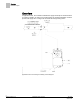
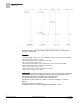
Overview Hardware Inputs Overview In Application 2521, the controller modulates the supply air damper of the terminal box for cooling or heating. In order for it to work properly, the central air-handling unit must provide cool supply air in cooling mode and warm air during heating mode. Application 2521 VAV Cooling and Heating Control Diagram. 4 Siemens Industry, Inc.
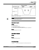
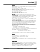
Overview Hardware Inputs Application 2521 control schedule. NOTES: 1. See Control Temperature Setpoints. 2. See Heating/Cooling Switchover.
Sequence of Operation Control Temperature Setpoints Sequence of Operation The following paragraphs present the sequence of operation for Application 2521, Base VAV - Cooling and Heating. Control Temperature Setpoints CTL STPT is Overridden If CTL STPT is overridden, that value is used regardless of any other settings. This disables the setpoint deadband feature. CTL STPT in Night Mode The controller is in Night mode if DAY.NGT = NGT and NGT OVRD = NGT.
Sequence of Operation Night Mode Override Switch Night Mode Override Switch If an override switch is present on the room temperature sensor and a value (in hours) other than zero has been entered into OVRD TIME, pressing the override switch resets the controller to DAY operational mode for the time period that is set in OVRD TIME. The status of NGT OVRD changes to DAY. After the override time elapses, the controller returns to night mode and the status of NGT OVRD changes back to NIGHT.
Sequence of Operation Control Loops FLOW STPT and FLOW % are relative to MIN and MAX STPTS of corresponding heating or cooling mode. Example If CLG FLOW MIN = 200 cfm, and CLG FLOW MAX = 1000 cfm, the minimum flow setpoint is (200 cfm/000 cfm) × 100% flow = 20%. When CLG LOOPOUT is 0%, FLOW STPT = 20% flow. [0% × (100% – 20%)] + 20% = 20% This ensures that the airflow out of the terminal box is no less than CLG FLOW MIN. When CLG LOOPOUT is 50%, FLOW STPT = 60% flow.
Sequence of Operation Calibration Example If HTG FLOW MIN = 100 cfm, and HTG FLOW MAX = 1000 cfm, the minimum flow setpoint is (100 cfm/1000 cfm) × 100% flow = 10%. When HTG LOOPOUT is 0%, FLOW STPT = 10% flow. [0% × (100% – 10%)] + 10% = 10% This ensures that the airflow out of the terminal box is not less than HTG FLOW MIN. When HTG LOOPOUT is 50%, FLOW STPT = 55% flow. [50% × (100% – 10%)] + 10% = 55% When HTG LOOPOUT is 100%, FLOW STPT = 100% flow.
Sequence of Operation Fail Mode Operation At the end of a calibration sequence, CAL AIR automatically returns to NO. A status of NO indicates that the controller is not in a calibration sequence. Floating Control Actuation Auto-correct In addition to the existing options for floating control actuator full stroke actions, all floating control actuators are provided with additional logic to fully drive open or closed when commanded to 100% or 0%.
Sequence of Operation Performing the Automated Fault Detection and Diagnostics Room temperature sensor failed—CHK STATUS = 1 1. The cable for the room temperature sensor may be unplugged or loose. Check both ends to ensure that the cable is securely seated. 2. Connect directly to the controller through the room temperature sensor connection on the VAV Actuator and check whether communication is possible. If so, the problem lies in the room temperature sensor or its cable.
Sequence of Operation Application Notes – CLG FLOW MAX 5. Motor setup information may be incorrect. Check the values of the following points and correct as needed: – MTR SETUP – MTR1 TIMING – DMPR ROT ANG 6. The box may not have been balanced correctly. Contact your local Siemens Industry representative. 7. The air velocity sensor may need calibration. Set CAL AIR to YES to run the calibration sequence.
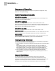
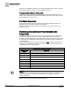
Sequence of Operation Wiring Diagram Wiring Diagram Application 2520 and 2521 Cooling Only Wiring Diagram. NOTE: There are no external I/Os for the Cooling Only Applications 2520 and 2521. 13 Siemens Industry, Inc.
Application 2521 Point Database Application 2521 Point Database Point Number Descriptor Factory Default (SI Units)2 Eng Units (SI Units) Slope (SI Units) Intercept (SI Units) On Text Off Text 1 CTLR ADDRESS 99 -- 1 0 -- -- 2 APPLICATION 2486 -- 1 0 -- -- {03} CHK STATUS -1 -- 1 -1 -- -- {04} ROOM TEMP 74.0 (23.44888) DEG F (DEG C) 0.25 (0.14) 48.0 (8.88888) -- -- {05} HEAT.COOL COOL -- -- -- HEAT COOL 6 DAY CLG STPT 74.0 (23.44888) DEG F (DEG C) 0.25 (0.
Application 2521 Point Database Point Number Descriptor Factory Default (SI Units)2 Eng Units (SI Units) Slope (SI Units) Intercept (SI Units) On Text Off Text {41} DO 1 OFF -- -- -- ON OFF {42} DO 2 OFF -- -- -- ON OFF {48} DMPR COMD 0 PCT 0.4 0 -- -- {49} DMPR POS 0 PCT 0.4 0 -- -- 51 MTR1 TIMING 95 SEC 1 0 -- -- 56 DMPR ROT ANG 90 -- 1 0 -- -- 58 MTR SETUP 0 -- 1 0 -- -- 59 DO DIR. REV 0 -- 1 0 -- -- 61 COOL TEMP 65.0 (18.
Application 2521 Point Database Point Number Descriptor Factory Default (SI Units)2 Eng Units (SI Units) Slope (SI Units) Intercept (SI Units) On Text Off Text 95 CAL SETUP 4 -- 1 0 -- -- 96 CAL TIMER 12 HRS 1 0 -- -- 97 DUCT AREA 1.0 (0.09292) SQ. FT (SQ M) 0.025 (0.002323) 0 -- -- 98 LOOP TIME 5 SEC 1 0 -- -- {99} ERROR STATUS 0 -- 1 0 -- -- 1) Points not listed are not used in this application.