
Application
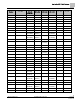
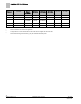
Table Of Contents

Sequence of Operation
Performing the Automated Fault Detection and Diagnostics
11
Siemens Industry, Inc. Application Note, App 2521 140-1218
2015-05-06
Room temperature sensor failed—CHK STATUS = 1
1. The cable for the room temperature sensor may be unplugged or loose. Check
both ends to ensure that the cable is securely seated.
2. Connect directly to the controller through the room temperature sensor connection
on the VAV Actuator and check whether communication is possible. If so, the
problem lies in the room temperature sensor or its cable. If not, the problem is with
the controller.
3. Contact your local Siemens Industry representative.
Room setpoint dial failed—CHK STATUS = 2
1. The cable for the room temperature sensor may be unplugged or loose. Check
both ends to ensure that the cable is securely seated.
2. The controller may be incorrectly set to use a setpoint dial with a sensor that does
not have the dial. If the sensor has no dial, change STPT DIAL from YES to NO.
3. Connect directly to the controller through the room temperature sensor connection
on the VAV Actuator and check whether communication is possible. If so, the
problem lies in the room temperature sensor or its cable. If not, the problem is with
the controller.
4. Contact your local Siemens Industry representative.
Air velocity sensor failed—CHK STATUS = 4
1. The sensor tubing may be blocked, leaking, or disconnected. Check for pinched,
disconnected, or cracked sensor tubing. Correct as needed.
2. The tubing connections for the air velocity sensor may be reversed. Re-pipe if HI
and LO connections are incorrect.
3. The sensor or the VAV Actuator may be faulty.
Controller could not reach CLG FLOW MIN or below—CHK STATUS =
8
1. The actuator may be loose on the shaft. Check that the set screw is fully tightened
against the damper shaft. Follow these torque guidelines:
– 70 ± 5 inch pounds—solid metal
– 37 ± 2 inch pounds—plastic, graphite, composite, or hollow metal (Hollow
metal shafts require an insert to prevent shaft damage.)
2. The tubing for the air velocity sensor may be pinched, disconnected, or cracked.
Check the tubing and correct as needed.
3. The tubing connections for the air velocity sensor may be reversed. Re-pipe if HI
and LO connections are incorrect.
4. Box sizing information may be incorrect. Check the values of the following points
and correct as needed:
– DUCT AREA
– FLOW COEFF
– CLG FLOW MIN