
Application

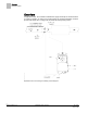
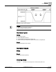
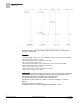
Table Of Contents

Sequence of Operation
Night Mode Override Switch
7
Siemens Industry, Inc. Application Note, App 2521 140-1218
2015-05-06
Night Mode Override Switch
If an override switch is present on the room temperature sensor and a value (in hours)
other than zero has been entered into OVRD TIME, pressing the override switch resets
the controller to DAY operational mode for the time period that is set in OVRD TIME.
The status of NGT OVRD changes to DAY. After the override time elapses, the
controller returns to night mode and the status of NGT OVRD changes back to NIGHT.
The override switch on the room sensor only affects the controller when it is in Night
mode.
Control Loops
The controller is controlled by three Proportional, Integral, and Derivative (PID) control
loops; two temperature loops and a flow loop.
The two temperature loops are a cooling loop and a heating loop. The active
temperature loop maintains room temperature at the value in CTL STPT. See
Control
Temperature Setpoints
.
Cooling Loop – The cooling loop generates cooling loopout which is then used to
generate FLOW STPT. FLOW STPT is the result of scaling the cooling loopout to the
appropriate range of values determined by flow minimum (CLG FLOW MIN) and flow
maximum (CLG FLOW MAX).
When CLG FLOW MIN ≠ 0 CFM, FLOWSTPT ≠ CLG LOOPOUT, the minimum flow
setpoint is (CLG FLOW MIN/CLG FLOW MAX) × 100% flow. And, FLOW STPT is
[CLG LOOPOUT × (100% – minimum setpoint)] + minimum setpoint.
The following figure describes how the flow setpoint is calculated:
FLOW STPT = [CLG LOOPOUT × (100% – % minimum setpoint)] + % minimum
setpoint.
Where percent minimum setpoint is:
% minimum setpoint = (CLG FLOW MIN/CLG FLOW MAX) x 100%