
Application

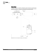
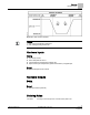
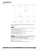
Table Of Contents

Sequence of Operation
Control Loops
8
Siemens Industry, Inc. Application Note, App 2521 140-1218
2015-05-06
FLOW STPT and FLOW % are relative to MIN and MAX STPTS of corresponding
heating or cooling mode.
Example
If CLG FLOW MIN = 200 cfm, and CLG FLOW MAX = 1000 cfm, the minimum flow setpoint is
(200 cfm/000 cfm) × 100% flow = 20%.
When CLG LOOPOUT is 0%, FLOW STPT = 20% flow.
[0% × (100% – 20%)] + 20% = 20%
This ensures that the airflow out of the terminal box is no less than CLG FLOW MIN.
When CLG LOOPOUT is 50%, FLOW STPT = 60% flow.
[50% × (100% – 20%)] + 20% = 60%
When CLG LOOPOUT is 100%, FLOW STPT = 100% flow.
[100% × (100% – 20%)] + 20% = 100%
Heating Loop – Generates heating loopout which is used to generate the FLOW STPT.
FLOW STPT is the result of scaling the heating loopout to the appropriate range of
values determined by HTG FLOW MIN and HTG FLOW MAX.
As described in the figure, the flow setpoint is calculated by:
FLOW STPT = [HTG LOOPOUT × (100% – % minimum setpoint)] + % minimum
setpoint.
Where percent minimum setpoint is:
% minimum setpoint = (HTG FLOW MIN/HTG FLOW MAX) x 100 %