
Application

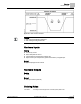
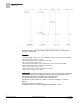
Table Of Contents

Sequence of Operation
Calibration
9
Siemens Industry, Inc. Application Note, App 2521 140-1218
2015-05-06
Example
If HTG FLOW MIN = 100 cfm, and HTG FLOW MAX = 1000 cfm, the minimum flow setpoint is
(100 cfm/1000 cfm) × 100% flow = 10%.
When HTG LOOPOUT is 0%, FLOW STPT = 10% flow.
[0% × (100% – 10%)] + 10% = 10%
This ensures that the airflow out of the terminal box is not less than HTG FLOW MIN.
When HTG LOOPOUT is 50%, FLOW STPT = 55% flow.
[50% × (100% – 10%)] + 10% = 55%
When HTG LOOPOUT is 100%, FLOW STPT = 100% flow.
[100% × (100% – 10%)] + 10% = 100%
Flow Loop – The flow loop maintains FLOW STPT by modulating the supply air
damper, DMPR COMD. The flow loop maintains the airflow between CTL FLOW MIN
and CTL FLOW MAX.
To enhance stable flow control, an advanced algorithm is used to calculate a
controllable setpoint as the value approaches zero cfm (lps).
When the controller is in cooling mode, CTL FLOW MIN = CLG FLOW MIN, and CTL
FLOW MAX = CLG FLOW MAX.
When the controller is in heating mode, CTL FLOW MIN = HTG FLOW MIN, and CTL
FLOW MAX = HTG FLOW MAX.
You can set CLG FLOW MIN equal to, but not greater than, CLG FLOW MAX. If the
minimum and maximum values are set equal, the flow loop becomes a constant
volume loop and loses its ability to control temperature.
FLOW is the input value for the flow loop. It is calculated as a percentage based on
where AIR VOLUME is between 0 cfm and CTL FLOW MAX. This percentage is
referred to as % flow.
If AIR VOLUME = 0 cfm, FLOW is 0% flow.
If AIR VOLUME = CTL FLOW MAX, FLOW is 100% flow.
The low limit of FLOW STPT is the percentage that corresponds to the volume given in
CTL FLOW MIN. This percentage can be calculated as:
(CTL FLOW MIN/CTL FLOW MAX) × 100% flow
The flow loop ensures that the supply air will not be less than CTL FLOW MIN.
Example
If CTL FLOW MIN = 250 cfm, and CTL FLOW MAX = 1000 cfm,
the low limit of FLOW STPT = (250 cfm/1000 cfm) × 100% flow
= 0.25 × 100% flow
= 25% flow.
Since 25% of 1000 cfm = 250 cfm, the minimum airflow out of the terminal box will be 250 cfm.
Calibration
Calibration of the controller’s internal air velocity sensor(s) is periodically required to
maintain accurate air velocity readings. CAL SETUP is set with the desired calibration
option during controller startup.
Depending on the value of CAL SETUP, calibration may be set to take place
automatically or manually. If CAL AIR = YES, calibration is in progress.