
Commissioning Instructions

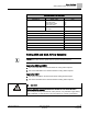
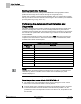
Table Of Contents
- Before You Begin
- Verifying Power to the Controller
- Setting the Application
- Enabling Actuators
- Selecting Automatic Calibration Option
- Setting Room Temperature Setpoints
- Setting Override Time
- Setting Duct Area
- Setting Flow Coefficient
- Setting MIN and MAX Airflow Setpoints
- Setting Controller Address
- Performing the Automated Fault Detection and Diagnostics

Before You Begin
Setting Controller Address
10
Siemens Industry, Inc. Start-up Procedures 140-1199
Restricted 2015-05-06
Setting Controller Address
Set the controller address by setting CTLR ADDRESS to the appropriate number.
(Addresses 00 through 98 are valid; 00 through 31 are typically used.)
Update each controller at the field panel immediately after you complete the controller
start-up procedures and have made all other changes to the controller’s point database
(including balancing, tuning, and so on.).
Performing the Automated Fault Detection and
Diagnostics
VAV ATEC controllers have a built-in checkout procedure that performs a basic fault
detection and diagnostic routine. It can be manually initiated at any time after the
controller has been installed. This procedure tests all of the necessary I/O and ensures
the controller can operate within the set airflow range, between CLG FLOW MIN and
CLG FLOW MAX.
To perform the checkout procedure, set CHK OUT to YES. When the procedure has
completed, CHK OUT returns to NO and the results display in CHK STATUS, Table
Possible Failure Value and Description
.
Possible Failure Value and Description
CHK STATUS
Values
Description
-1 Checkout procedure has not been run since last controller initialization.
0 No errors found.
1 RTS failed.
2 Room Setpoint dial failed (If STPT DIAL = YES).
4 AVS failed.
8 Controller could not reach CLG FLOW MIN or below.
16 Controller could not reach CLG FLOW MAX or above.
32 Controller did not read low (zero) flow when damper closed.
NOTE:
Multiple failures are added together and displayed as one value. For example, if the
RTS failed (1) and the controller could not reach CLG FLOW MAX (16), CHK
STATUS displays 17.
Failure codes indicate the following possible problems.
Room temperature sensor failed—CHK STATUS = 1
1. The cable for the room temperature sensor may be unplugged or loose. Check
both ends to ensure that the cable is securely seated.
2. Connect directly to the controller through the room temperature sensor connection
on the VAV Actuator and check whether communication is possible. If so, the
problem lies in the room temperature sensor or its cable. If not, the problem is with
the controller.