
Commissioning Instructions

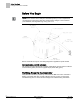
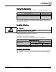
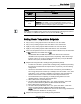
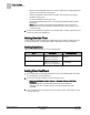
Table Of Contents
- Before You Begin
- Verifying Power to the Controller
- Setting the Application
- Enabling Actuators
- Selecting Automatic Calibration Option
- Setting Room Temperature Setpoints
- Setting Override Time
- Setting Duct Area
- Setting Flow Coefficient
- Setting MIN and MAX Airflow Setpoints
- Setting Controller Address
- Performing the Automated Fault Detection and Diagnostics

Before You Begin
Verifying Power to the Controller
4
Siemens Industry, Inc. Start-up Procedures 140-1199
Restricted 2015-05-06
Before You Begin
NOTE:
Update each controller at the field panel immediately after you have completed the
controller start-up procedures and have made all other changes to the controller’s
point database, including balancing, tuning, and so on.
Generic Controller I/O Layout. See
Wiring Diagram
for application specific details.
Communication and DO Indicators
The Actuating Terminal Equipment Controller (ATEC) Base VAV has LEDs to indicate
communication (yellow) and the DO (digital output) status BST (green).
Verifying Power to the Controller
Verify that the controller is powered up. Check that the BST LED on the controller is
flashing. If the BST LED does not flash ON/OFF once per second, see the
iKnow
Troubleshooting Tool
or contact Technical Support for troubleshooting information.