
Commissioning Instructions

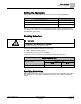
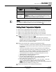
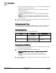
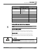
Table Of Contents
- Before You Begin
- Verifying Power to the Controller
- Setting the Application
- Enabling Actuators
- Selecting Automatic Calibration Option
- Setting Room Temperature Setpoints
- Setting Override Time
- Setting Duct Area
- Setting Flow Coefficient
- Setting MIN and MAX Airflow Setpoints
- Setting Controller Address
- Performing the Automated Fault Detection and Diagnostics

Before You Begin
Setting the Application
5
Siemens Industry, Inc. Start-up Procedures 140-1199
Restricted 2015-05-06
Setting the Application
Add the TEC to your job database and select one of the following applications.
Application Description
Application Number
VAV Cooling Only 2520
VAV Cooling or Heating 2521
VAV Slave Mode 2486
After you set the application, the controller goes through a shut-down/load sequence
as it switches from slave mode to the application selected. After the application loads,
the calibration cycle begins.
Enabling Actuators
CAUTION
The controller's DOs control only 24 Vac loads.
The maximum rating is 12 VA for each DO.
The point(s) that determine actuator run times are:
MTR 1 TIMING (damper actuator)
Your application may not have or use MTR2.
Use and/or to set run time(s) for the actuator(s) used by your application.
Damper Actuator Run Time
Damper Actuator
Setting (seconds)
50 Hz
60 Hz
GDE131.1 125 90
Specifying Motor Setup
MTR SETUP determines which actuators are controlled by the application and whether
they are direct or reverse acting. Set MTR SETUP according to Table
MTR SETUP
Values
.