
Commissioning Instructions


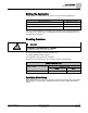
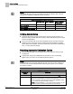
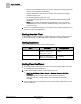
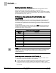
Table Of Contents
- Before You Begin
- Verifying Power to the Controller
- Setting the Application
- Enabling Actuators
- Selecting Automatic Calibration Option
- Setting Room Temperature Setpoints
- Setting Override Time
- Setting Duct Area
- Setting Flow Coefficient
- Setting MIN and MAX Airflow Setpoints
- Setting Controller Address
- Performing the Automated Fault Detection and Diagnostics

Before You Begin
Selecting Automatic Calibration Option
6
Siemens Industry, Inc. Start-up Procedures 140-1199
Restricted 2015-05-06
NOTE:
When MTR SETUP is changed, all enabled actuators will calibrate. Wait until each
actuator has completed its calibration before continuing.
Motor Enable/Reverse Values for MTR SETUP.
Motor 1 Not Used
Motor 1 Enabled
Motor 1 Enabled
and Reversed
Motor 2 Not Used
0 1 3
Motor 2 Enabled
4 5 7
Motor 2 Enabled and Reversed
12 13 15
Verifying Actuator Setup
1. Command all actuators closed. Verify that they close and remain closed. If not,
adjust the setting for MTR SETUP according to Table
MTR SETUP Value for Most
Common Configurations
.
2. If any of the actuators still do not close completely, then the actuators have been
installed or set up incorrectly. See the Actuating Terminal Equipment Controller
(ATEC) Base VAV Installation Instructions (540-1035), the iKnow Troubleshooting
Tool, or contact Technical Support.
Selecting Automatic Calibration Option
1. Using the following table, set CAL SETUP to the value that best meets your job
requirements.
2. If appropriate, change CAL TIMER from the default of 12 hours. This setting
applies only if your choice for CAL SETUP includes Option 4.
NOTE:
The air velocity sensor should be calibrated at least once every 24 hours. Make sure
that the sensor has been calibrated before balancing takes place, as this will affect
the balancer’s results.
CAL SETUP Options.
CAL SETUP
(value)
Description
0 Calibration occurs ONLY when the point CAL AIR is set to
YES
.
1 Calibration occurs when the field panel commands a Day/Night mode
changeover. Actual calibration is subject to a time delay of 0, 1, 2, or 3
minutes. This delay is determined by the point CTLR ADDRESS divided
by 4. The remainder is the time delay in minutes.
Example:
If CTLR ADDRESS = 11, then the controller will wait 3 minutes
(11 ÷ 4 = 2 R3) after it receives the Day/Night mode changeover