
Commissioning Instructions

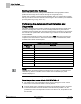
Table Of Contents
- Before You Begin
- Verifying Power to the Controller
- Setting the Application
- Enabling Actuators
- Selecting Automatic Calibration Option
- Setting Room Temperature Setpoints
- Setting Override Time
- Setting Duct Area
- Setting Flow Coefficient
- Setting MIN and MAX Airflow Setpoints
- Setting Controller Address
- Performing the Automated Fault Detection and Diagnostics

Before You Begin
Setting Room Temperature Setpoints
7
Siemens Industry, Inc. Start-up Procedures 140-1199
Restricted 2015-05-06
CAL SETUP Options.
CAL SETUP
(value)
Description
command before beginning the calibration routine.
2 Calibration occurs immediately after the override switch is pressed.
4
(factory default
value)
Calibration occurs on the time interval set in the point CAL TIMER.
Example:
If CAL TIMER = 12, then the calibration period is 12 hours.
Actual calibration is subject to a time delay based on the value of CTLR
ADDRESS. See the example in Option 1 in this table.
NOTE:
Since these are additive values, options can be combined by summing their numbers.
For example, to calibrate in Options 1 and 2, set CAL SETUP to
3
.
Setting Room Temperature Setpoints
Day (or OCC) cooling setpoint: DAY CLG STPT or OCC CLG STPT
Day (or OCC) heating setpoint: DAY HTG STPT or OCC HTG STPT
Night (or UOC) cooling setpoint: NGT CLG STPT or UOC CLG STPT
Night (or UOC) heating setpoint: NGT HTG STPT or UOC HTG STPT
1. If the room temperature sensor has a setpoint dial that will be used, set STPT DIAL
to YES. Otherwise, leave STPT DIAL to NO.
– Set RM STPT MIN and RM STPT MAX for the minimum and maximum
allowable room temperature setpoint values, respectively. Valid values range
from 55° to 95°F (13° to 35°C). Default values are 55°F (13°C) for RM STPT
MIN and 90°F (32°C) for RM STPT MAX.
2. Setpoint dial configured with a heating/cooling deadband (default).
– To allow the controller to operate with a heating/cooling deadband (functioning
the same as provided when the setpoint dial is not present), use the following
configuration:
– Set the DAY HTG STPT less than the DAY CLG STPT by the deadband (or
zero energy band) that is desired. (For example, DAY HTG STPT = 70°F; DAY
CLG STPT = 74°F, providing a deadband of 4 degrees). Only the difference
between these values is used to determine What setpoint will be used.
– As described below, the setpoint(s) for heating/cooling will be 1/2 of the
deadband above or below the setpoint dial value.
When HEAT.COOL equals HEAT, then:
CTL STPT will equal RM STPT DIAL – 0.5 * (DAY CLG STPT – DAY HTG
STPT) and will be limited by RM STPT MIN and RM STPT MAX.
When HEAT.COOL equals COOL, then:
CTL STPT will equal RM STPT DIAL + 0.5 * (DAY CLG STPT – DAY HTG
STPT) and will be limited by RM STPT MIN and RM STPT MAX.
NOTE: A space where the deadband is used can be more energy efficient than
a space where the deadband is not being used.
3. Setpoint dial configured for zero heating/cooling deadband.