
Installation Instructions

Document No. 540-569
Installation Instructions
July 15, 2009
• Transformer P/N 10041BCWB: maximum
6VA per DO/ maximum 36 VA total.
• Transformer P/N AM-2483-OA: maximum
6VA per DO/ maximum 16 VA total.
3. The room temperature sensor (RTS) is installed
inthesameroomastheTEC.
4. Connection from the TEC to the APOGEE field
panel is maximum 4000 feet, 24 AWG minimum.
5. Wiring Range:
• Transformer: primary 14 AWG
• 24 Vac Input Power: 14 to 18 AWG
• DO:AI:18to20AWG
•DI:18AWG
• LAN:20to24AWG
•RST:24AWG
6. Refer to the following documents when used
configuring for smoke control application:
• 125-1806: Smoke Control Systems
Application and Engineering Manual
• 125-1816: Smoke Control System
Application Guide
• 125-1817: NFPA and UL Standards
Relevant to Smoke Control System
Application Guide
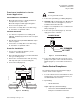
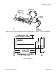
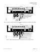
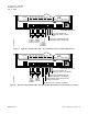
CE Compliance
If CE compliance is required, a ferrite filter must be
placed approximately 1 cm from the end of the cable
being shielded (RTS cable[ and the point wiring for
AI3]) (Figure 4).
TEC0320R3
1- 2 cm
1
Place the filter 1-2 cm
from the end of the cable
or wiring to be shielded.
2
Wind the cable tightly
twice around the filter.
3
Close the filter and wrap
with a zip tie.
Figure 4. Ferrite filter(s) for CE Compliance.
Page 4 of 12 Siemens Building Technologies, Inc.