
Installation Instructions

Document No. 540-569
Installation Instructions
July 15, 2009
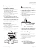
Wiring Diagrams
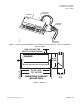
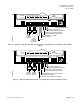
24 VDC
POWER
SUPPLY
4-20 mA
SENSOR
ENTIRE CIRCUIT
MUST BE ISOLATED
WITH NO EARTH GROUND,
INCLUDING THE 4-20 mA
SENSOR
DO NOT use the same transformer to power both the sensor and controller.
Each 4-20mA sensor requires a SEPARATE, dedicated 24 VDC power supply.
-+
-
+
TEC0429R2
ANALOG INPUT
TERMINATIONS
CAUTION:
Figure 7. Special Wiring Requirements for 4–20 mA
Sensors.
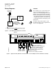
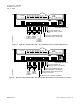
CAUTION:
The controller’s DOs control 24 Vac loads
only. The maximum rating is 6 VA for
each DO. Use an interposing 24 Vac relay
module (such as P/N [550-054, 550-048,
550-050, 550-052]) for any of the following:
• VA requirements higher than maximum
• Separate transformers to power the load
• Power limited Direct Current (DC) power
requirements
The 24Vac relay module and the circuit
described in Figure 7 are not applicable for
smoke control application.
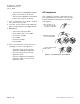
24 V-AC
C H
TX
RX
FLN
TRUNK
+ - S
BST
RTS
DO 1
NO C
DO 2
NO C
DO 3
NO C
DO 4
NO C
DO 5
NO C
DO 6
NO C
DI 3
AI 3
DI 2
1 2 3 4 5 6 7 8 9 10 11 12 13 14 15 16
1 2 3 4 5 6 7 8 9 10 11 12 13 14 15 16
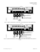
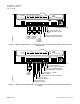
ROOM TEMPERATURE SENSOR
SPARE AI (100K THERMISTOR ONLY); OR,
SPARE DI (DRY CONTACT CLOSURE ONLY)
WALL SWITCH (OPTIONAL); OR,
SPARE DI (DRY CONTACT CLOSURE ONLY)
AUTOZERO MODULE OR ELECTRIC HEAT STAGE 2
(OPTIONAL); OR, SPARE DO
TEC2035AWD-SR1
CW
COMMON
CCW
Y1 G
Y2
Y1 G
Y2
CW
COMMON
CCW
ELECTRIC HEAT STAGE 1 (OPTIONAL); OR, SPARE DO
DAMPER
ACTUATOR
DAMPER
ACTUATOR
(HOT DUCT)(COLD DUCT)
Figure 8. Application 2035 (Dual Duct Constant Volume – Two Inlet Damper Actuators with Electric Reheat).
Page 6 of 12 Siemens Building Technologies, Inc.