APOGEE Heat Pump Controller - Multi-Stage Owner’s Manual 125-1953 Rev.
ii
Rev. BA, June 2006 NOTICE The information contained within this document is subject to change without notice and should not be construed as a commitment by Siemens Building Technologies, Inc. Siemens Building Technologies, Inc. assumes no responsibility for any errors that may appear in this document. All software described in this document is furnished under a license and may be used or copied only in accordance with the terms of such license.
IV
Table of Contents How to Use This Manual...............................................................................................V Manual Organization ...............................................................................................V Manual Conventions ...............................................................................................V Manual Symbols......................................................................................................VI Datamate Software .....
Heat Pump Controller - Multi-Stage Owner’s Manual Application 2274: Multiple Heating and Cooling Heat Pump with Mixed Air and Internal Reversing Valve Control........................................................13 Compressor/Electric Heat Staging..........................................................................13 Application Notes ....................................................................................................13 Application 2290: Heat Pump ControlIer Multi-Stage Slave Mode...
How to Use This Manual This manual is written for the owner and user of the Siemens Building Technologies, Inc. Heat Pump Controller—Multi-Stage, often referred to as controller for the remainder of this manual. This manual is designed to help you become familiar with the controller and its applications. This chapter covers manual organization, manual symbols and conventions used in the manual, and how to access help.
Heat Pump Controller - Multi-Stage Owner’s Manual Manual Symbols The following table lists symbols that are used to draw your attention to important information. Notation Symbol Meaning CAUTION: Indicates that equipment damage or loss of data may occur if the user does not follow a procedure as specified. WARNING: Indicates that personal injury or loss of life may occur to the user if a procedure is not performed as specified.
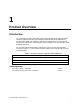
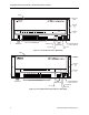
1 Product Overview Introduction The Heat Pump Controller—Multi-Stage is the Siemens Building Technologies APOGEE® Terminal Equipment Controller used in multiple compressor heat pump applications. lt provides Direct Digital Control (DDC) for two heat pump applications. The controller can operate as an independent, stand-alone DDC room controller or it can be networked with an APOGEE® field panel. The controller provides all termination, input/output, system, and local communication connections (Figure 1-1).
APOGEE Heat Pump Controller—Multi-Stage Owner's Manual COVER CONTROLLER BOARD MOUNTING HOLE (2) 24 V-AC C H TEC0167R4 C H POWER TRUNK TERMINATIONS DO 1 DO 2 DO 3 DO 4 DO 5 DO 6 DO 7 DO 8 DI 3 NO C NO C NO C NO C NO C NO C NO C NO C AI 3 DI 2 DI 4 FLN TRUNK AO 1 + - 1 2 3 4 5 6 7 8 9 10 11 12 13 14 15 16 17 18 19 20 21 22 23 24 TX RX 1 2 3 4 5 6 7 8 9 10 11 12 13 14 15 16 17 18 19 20 21 22 23 24 + - S + - BST MOUNTING RAIL RTS S DO LEDS INPUT / OUTPUT TERMINATIONS TRANSMIT LED FLN TR
Product Overview Hardware Inputs Analog • Mixed air temperature sensor (optional) • Room Temperature Sensor (RTS) • Room temperature setpoint dial (optional) • Heat pump alarm (optional) • Night mode override (optional) • Wall switch (optional) Digital Hardware Outputs Analog • Damper actuator (spring return) (optional) Application Digital • Compressor 1 2273 • Compressor 2 (optional); or stage 3 electric heat (optional) 2273 • Compressor 3 (optional); or stage 2 electric heat (option
APOGEE Heat Pump Controller—Multi-Stage Owner's Manual Power Wiring The controller is powered by 24 Vac. Power wiring connects to the two screw terminals on the controller labeled “C” (Common) and “H” (Hot) on the terminal block labeled “24 VAC”. No earth ground connection is required (Figure 1-3). Communication Wiring The controller connects to the field panel by means of a Floor Level Network (FLN) trunk.
Product Overview Temperature Sensors An electronic Room Temperature Sensor (RTS) or an optional auxiliary temperature sensor may be used with the Heat Pump Controller—Multi-Stage. Room Temperature Sensor The Terminal Equipment Controller RTS connects to the controller by means of a cable preterminated at both ends with a 6-conductor RJ-11 plug-in connector. See Figure 1-1 for the location of the RTS/Man-Machine lnterface (MMl) port.
APOGEE Heat Pump Controller—Multi-Stage Owner's Manual 6 Siemens Building Technologies, Inc.
2 Applications Basic Operation The Heat Pump Controller—Multi-Stage provides Direct Digital Control (DDC) technology for multiple compressor heat pump applications. Temperature control varies with the application. If present, mixed air temperature control and up to three stages of electric heat or staged heating and cooling can be provided.
APOGEE Heat Pump Controller—Multi-Stage Owner's Manual The mixed air loop controls only the mixed air portion of the application. The mixed air damper motor can be either a spring return or floating control damper motor. • For a spring return damper, the mixed air loop will control the damper through its 0 to 10 volt analog output and the digital outputs will be spare. • For a floating control damper the mixed air loop will control the damper through DO 1 and DO 2, and the analog output will be a spare.
Applications Heating and Cooling Switchover The heating/cooling switchover determines whether the controller is in heating or cooling mode by monitoring the room temperature and the demand for heating and cooling (as determined by the temperature control loops). Electric Reheat CAUTION: Verify that the equipment is supplied with safeties by others to ensure that there is airflow across the heating coils when they are to be energized.
APOGEE Heat Pump Controller—Multi-Stage Owner's Manual Power Failure Recovery Upon return from a power failure, the heating and cooling compressors are kept off, the electric heat (if used) is kept off and the fan is kept off. In addition to the equipment being OFF, both cooling and heating loops are set to 0. This situation will remain in effect until the power failure recovery period for this controller is over. The controller returns to normal control when its power failure recovery period is over.
Applications Application 2273: Multiple Compressor Heat Pump with Reversing Valve Control and Mixed Air Control In Application 2273 (Figure 2-1), the controller controls a multi-stage heat pump with a reversing valve controlled by the heat pump controller. In addition to compressors, this heat pump may also be equipped with electric heat for auxiliary heat and mixed air control for free cooling. The mixed air control can use either a spring return or a floating control damper motor.
APOGEE Heat Pump Controller—Multi-Stage Owner's Manual 1. In this application, the maximum configurations are as follows: • The maximum of CMP TOTL (Point 75) = 3. • The maximum of EHTG STG CNT (Point 76) = 3. • The maximum of CMP TOTL plus EHTG STG CNT = 4. If these limits are exceeded, CMP TOTL will be set to 0 and EHTG STG CNT will be set to 0. These points will remain at 0 until they are set correctly.
Applications Application 2274: Multiple Heating and Cooling Heat Pump with Mixed Air and Internal Reversing Valve Control ln Application 2274, (Figure 2-2) the controller controls one or two heating compressors for heating and one or two cooling compressors for cooling. The reversing valve is controlled internally by the heat pump. ln addition to compressors, this heat pump may also be equipped with electric heat for auxiliary heat and mixed air control for free cooling.
APOGEE Heat Pump Controller—Multi-Stage Owner's Manual SUPPLY AIR COMPRESSOR 1 COMPRESSOR 2 REVERSING VALVE* REVERSING VALVE* ELECTRIC HEAT (OPTIONAL) HEATING / COOLING O.A. N.C. COIL COIL O.A. DAMPER** (OPTIONAL) FAN N.O. WATER SOURCE MIXED AIR TEMPERATURE SENSOR (OPTIONAL) COIL COIL R.A. R.A. DAMPER** (OPTIONAL) * CONTROLLED INTERNALLY BY THE HEAT PUMP ** THE O.A. AND R.A. DAMPERS MUST BE MECHANICALLY LINKED.
Applications Application 2290: Heat Pump ControlIer Multi-Stage Slave Mode Application 2290 is the slave mode application for the Heat Pump Controller—Multi-Stage (P/N 540-505). Slave mode is the default application that comes up when power is first applied to the controller. Slave mode provides no control. lts purpose is to allow the operator to perform equipment checkout before a control application is put into effect and to set some basic controller parameters (CTLR ADDRESS, APPLlCATlON, etc.).
APOGEE Heat Pump Controller—Multi-Stage Owner's Manual 16 Siemens Building Technologies, Inc.
3 Point Database Overview This chapter presents a description of the Heat Pump Controller—Multi-Stage point database including point descriptors, point addresses, and a listing of applications in which each point is found. Description Address Application CTLR ADDRESS 01 2273, 2274, 2290 ldentifies the controller on the FLN trunk. APPLICATION 02 2273, 2274, 2290 Identification number of the program running in the controller.
APOGEE Heat Pump Controller—Multi Stage Owner's Manual Description Address Application Description RM STPT MlN 11 2273, 2274 Minimum temperature setpoint in degrees that the controller can use from the setpoint dial. This overrides any temperature setpoint from the setpoint dial that falls below this minimum. Valid entry range: 48° to 95°F (9° to 35°C) RM STPT MAX 12 2273, 2274 Maximum temperature setpoint in degrees that the controller can use from the setpoint dial.
Point Database Description Address Application Description Dl OVRD SW 19 2273, 2274, 2290 Actual indication of the status of the override switch (not physically available on all temperature sensor models) at the room temperature sensor. ON indicates that the switch is being pressed. OFF indicates that the switch is released.
APOGEE Heat Pump Controller—Multi Stage Owner's Manual Description Address Application Description CLG CMP1 OFF 31 2274 Value, in percent, that the cooling temperature control loop output must go below for cooling compressor 1 to turn OFF. Actual turn off is subject to the CLG1 MlN ON (Point 33) time being expired. CLG1 MlN OFF 32 2274 Minimum time, in minutes, that cooling compressor 1 will remain OFF before turning ON.
Point Database Description Address Application DO 3 43 2290 Digital output 3 controls a 24 Vac load with an ON or OFF status. lf Motor 2 is enabled, DO 3 is coupled with DO 4 to control an actuator. ELEC HEAT 43 2274 This output controls the contact for the first stage of electric heat and has a status of ON or OFF. ELEC HEAT 1 43 2273 This output controls the contact for the first stage of electric heat and has a status of ON or OFF.
APOGEE Heat Pump Controller—Multi Stage Owner's Manual Description Address Application Description DO 8 50 2290 FAN 50 2273, 2274 Digital output used to control the fan. ON indicates the DO is energized; OFF indicates the DO is de-energized. MTR TIMING 51 2273, 2274 Time required for the damper actuator to travel from full closed to the full open position. MTR1 TIMING 51 2290 Time required for the Motor 1 actuator to travel from full closed to the full open position.
Point Database Description Address Application HTG P GAIN 67 2273, 2274 Proportional gain value for the heating temperature control loop. HTG I GAIN 68 2273, 2274 Integral gain value for the heating temperature control loop. HTG D GAIN 69 2273, 2274 Derivative gain value for the heating temperature control loop. HTG BIAS 70 2273, 2274 Biasing of the heating temperature control loop. See HTG LOOPOUT (Point 80).
APOGEE Heat Pump Controller—Multi Stage Owner's Manual Description Address Application CMP1 OFF 83 2273 Value, in percent, that the active temperature control loop output must go below for compressor 1 to turn OFF. Actual turn off is subject to the CMP1 MlN ON (Point 88) time being expired. HTG CMP1 OFF 83 2274 Value, in percent, that the heating temperature control loop output must go below for heating compressor 1 to turn OFF.
Point Database Description Address Application EHEAT 2 ON 94 2273 Value, in percent, that the heating loopout must exceed for the second stage of electric heat to turn ON. EHEAT 3 ON 95 2273 Value, in percent, that the heating loopout must exceed for the third stage of electric heat to turn ON. CAL TIMER 96 2273, 2274, 2290 Time interval, in hours, between the calibration sequence. LOOP TIME 98 2273, 2274 ERROR STATUS 99 2273, 2274, 2290 Siemens Building Technologies, Inc.
APOGEE Heat Pump Controller—Multi Stage Owner's Manual 26 Siemens Building Technologies, Inc.
4 Troubleshooting This chapter describes corrective measures you can take should you encounter a problem when using a Heat Pump Controller—Multi-Stage. You are not required to do any controller troubleshooting. You may want to contact your local Siemens Building Technologies representative if a problem occurs or you have any questions about the controller. NOTE: When troubleshooting, record what the problem is and what actions were performed immediately before the problem occurred.
APOGEE Heat Pump Controller – Multi-Stage Owner's Manual Ordering Replacement Parts If a controller is not operating correctly, order a new controller. The product number for ordering a replacement controller is the controller product number preceded by an "R".
Glossary Overview The glossary contains terms and acronyms that are used in this manual. For definitions of point database descriptors, see Chapter 3, Point Database. For definitions of commonly used terms as well as acronyms and abbreviations associated with the APOGEE Automation System, see the Siemens Building Technologies Technical Glossary of Building Controls Terminology and Acronyms, (125-2185). This book is available from your local Siemens Building Technologies representative. Al Analog Input.
APOGEE Heat Pump Controller — Multi-Stage Owner's Manual DO Digital Output. Physical output point that generates a two-state signal (that is, ON/OFF, OPEN/CLOSED, YES/NO, etc.). English units Foot-pound-second system of units for weights and measurements. equipment controller FLN device which provides additional point capacity to a field panel or provides individual room or mechanical equipment control. The Heat Pump Controller — Multi-Stage is an equipment controller.
Glossary ON text Text indicating the energized state of a digital point (for example, ON, OPEN, YES). override switch Button on Room Temperature Sensor that can be pressed by an occupant to change the status of a room from night mode to day mode for a predetermined time. PID Proportional, lntegral, and Derivative. RTS Room Temperature Sensor. Sl units Systeme International d'Unites. The international metric system.
APOGEE Heat Pump Controller — Multi-Stage Owner's Manual unbundle Term used to describe the entering of a point that resides in a controller's database into the field panel's database so that it can be monitored at or controlled from the field panel. 32 Siemens Building Technologies, Inc.
Index A C actuator .......................................................... 0-5 address descriptions .................................... 3-18 AI (see analog input) algorithm ......................................................G-30 analog input.......................................... 0-2, G-30 analog output ....................................... 0-3, G-30 AO ........................................ (see analog output) application notes ................................................
APOGEE Heat Pump Controller — Multi-Stage Owner's Manual Floor Level Network (FLN)............................. 0-4 H hardware power wiring ............................................... 0-4 relay module ............................................... 0-6 hardware, inputs and outputs......................... 0-2 heat pump controller—multi-stage ................. 0-1 I inputs and outputs analog .................................................. 0-2, 0-3 digital ...........................................
Index V W valve 2-position heating ....................................... 2-9 valve, reversing ............................................ 2-12 wiring communication wiring..................................0-4 power wiring ................................................0-4 Siemens Building Technologies, Inc.