
Operating Instructions
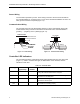
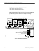
Table Of Contents
- Manual Organization
- Manual Conventions
- Manual Symbols
- Datamate Software
- Getting Help
- Where To Send Comments
- Introduction
- Basic Operation
- Application 2273: Multiple Compressor Heat Pump with Reversing Valve Control and Mixed Air Control
- Application 2274: Multiple Heating and Cooling Heat Pump with Mixed Air and Internal Reversing Valve Control
- Application 2290: Heat Pump ControlIer Multi Stage Slave Mode
- Overview
- Overview

APOGEE Heat Pump Controller—Multi-Stage Owner's Manual
Power Wiring
The controller is powered by 24 Vac. Power wiring connects to the two screw terminals on
the controller labeled “C” (Common) and “H” (Hot) on the terminal block labeled “24 VAC”. No
earth ground connection is required (
Figure 1-3).
Communication Wiring
The controller connects to the field panel by means of a Floor Level Network (FLN) trunk.
Communication wiring connects to the three screw terminals on the controller labeled “+”
(positive), “-“ (negative), and “S” (Shield) (
Figure 1-4).
C H EGRND WHEN THIRD TER-
MINATION IS PRESENT
24 V COMMON
24 V HOT
E GRND
POWER TRUNK
TEC0471R2
FLN TRUNK
+-
S
(SHIELD) (SHIELD)
(+)
(+)
(-)
(-)
TEC0470R1
Figure 1-3. Power Wiring. Figure 1-4. Communication Wiring.
Controller LED Indicators
The controller has eleven Light Emitting Diode (LED) indicators that give off a green glow.
(
Figure 1-1). Table 1-2 lists the LED type, the abbreviation on the controller, and the
indication of each LED.
Table 1-2. Controller LEDs.
LED Type Label
(if present)*
LED
Number
Indication
DO LED 1–LED 8 1 to 6, 10, 11 Indicates the ON/OFF status of the DO associated with it. A
glowing LED indicates that the DO is energized.
Receive RX 7 Indicates, when flashing, that the controller is receiving
information from the field panel.
Transmit TX 8 Indicates, when flashing, that the controller is transmitting
information to the field panel.
Basic Sanity
Test
BST 9 Indicates, when flashing ON and OFF once per second, that
the controller is functioning properly.
* Some LED labels and numerals may be hidden by the controller cover.
4 Siemens Building Technologies, Inc.